Huawei NetCol8000-C070 User manual

NetCol8000-C(070, 130, 190) In-room
Chilled Water Smart Cooling Product
Quick Guide
Issue: 06
Part Number: 31500CWQ
Date: 2022-12-15
HUAWEI DIGITAL POWER TECHNOLOGIES CO., LTD.
1
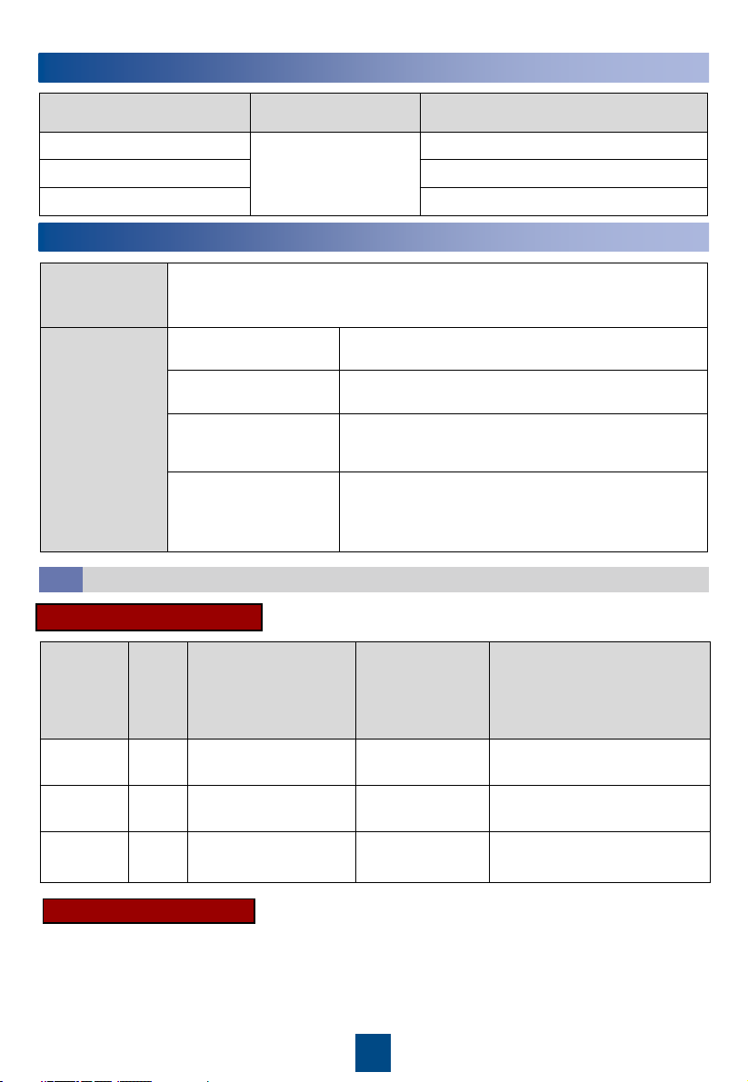
1Product Overview
Materials
Delivered with
the Equipment
Cord end terminal of the power cable connecting to the indoor unit (2.5 mm2
or 4 mm2or 6 mm2), OT ground terminal of the power cable to the indoor unit
(2.5 mm2or 6 mm2)
Engineering
Purchasing
Drainpipe Rigid pipe: made of PP-R material; 3/4 inch outer
screw thread to rigid pipe connector
Water inlet and outlet
pipe
DN50 rigid pipe with an G 2 inch external threaded
connector
(Optional) Water inlet
pipe for the wet film
humidifier
Rigid pipe: made of PP-R material; G 3/4 inch inner
screw threads to rigid pipe conversion adapter
Other Hoop iron, cable tie, push mount tie, network cable
for teamwork, power cable, base, pipe support,
thermal insulation foam, dedicated glue for thermal
insulation foam, thread sealant
2Engineering Materials
Cables
2.1
Product Model Pipe Routing Dimensions Without Packing (H x W x
D) (mm)
NetCol8000-C070 Upflow: routed from
bottom or side
Downflow: routed from
bottom
2000 x 900 x 1000 (single-door)
NetCol8000-C130 2000 x 1800 x 1000 (double-door)
NetCol8000-C190 2000 x 2700 x 1000 (triple-door)
Model Setup Maximum Current
(cooing only/full
configuration)
Recommended
Switch (cooing
only/full
configuration)
Cable Diameter (cooing
only/full configuration)
NetCol8000
-C070
Dual
route
Active: 7.3 A/16.5 A
Standby: 7.3 A/7.3 A
Active: C16/C32
Standby: C16/C16
Active: 4 x 2.5 mm2/4 x 4 mm2
Standby: 4 x 2.5 mm2/4 x4 mm2
NetCol8000
-C130
Dual
route
Active: 14 A/32.3 A
Standby: 14 A/14 A
Active: C25/C50
Standby: C25/C25
Active: 4 x 4 mm2/4 x 6 mm2
Standby: 4 x 4 mm2/4 x 6 mm2
NetCol8000
-C190
Dual
route
Active: 20.7 A/39 A
Standby: 20.7 A/20.7 A
Active: C40/C63
Standby: C40/C40
Active: 4 x 4 mm2/4 x 6 mm2
Standby: 4 x 4 mm2/4 x 6 mm2
Active/Standby Power Cable
Equipotential Ground Cable
Equipotential ground cable: 6 mm2outdoor copper cable.
Copyright © Huawei Digital Power Technologies
Co., Ltd. 2022. All rights reserved.

2
3Installing the Cabinet
1. Read the related user manual or instructions before installing the NetCol8000-C.
2. Use insulated tools when installing the equipment.
3. The downflow NetCol8000-C must be installed in the equipment room with a raised floor.
4. Only engineers certified by the manufacturer or its agent are allowed to install, commission,
and maintain the smart cooling product. Otherwise, personal injury or equipment damage
may occur, and the resulting smart cooling product faults are beyond the warranty scope of
Huawei.
5. The electricians onsite must be qualified.
6. If cabinets are not placed abreast, the height of the raised floor should be greater than 550
mm for downflow units, and the height of the raised floor should be greater than 300 mm
for upflow units.
7. If cabinets are placed abreast and pipes are routed from the bottom, the height of the raised
floor should be greater than 800 mm.
8. During installation, place the packaged top panel on the top of the cabinet to prevent the
dust. Remove the top panel before the power-on commissioning.
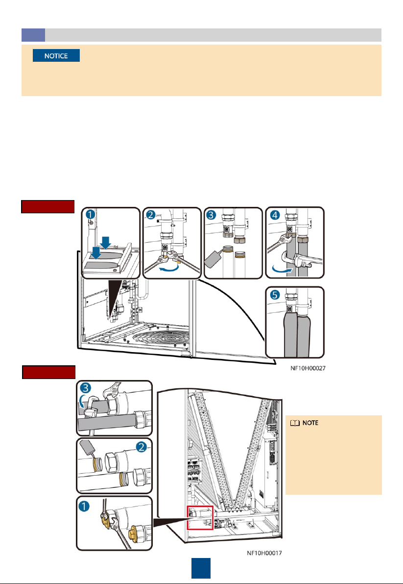
•The equipment is charged with nitrogen before delivery. Rotate the exhaust valve
counterclockwise. If there is a hiss sound, the system is well sealed, and you need to open
the exhaust valve to exhaust the nitrogen. If there is no hiss sound, contact Huawei technical
support.
•After nitrogen is exhausted, remove the desiccant bag bound to the fan.
•You can open or close the exhaust valve using a flat-head screwdriver.
Checking the Nitrogen Pressure and Exhausting Nitrogen
3.1
1. The height of a U-shaped pipe clamp equals
the diameter of the pipe with thermal
insulation foam minus 5 mm. The pipe
supports are to be purchased.
2. The material for pipe supports and clamps
should meet outdoor application
requirements.
3. Install a support every 2500 mm in the
straight sections of pipes, and 1000 mm away
from each bending point in the turning
section.
Pipe Support
2.2
3
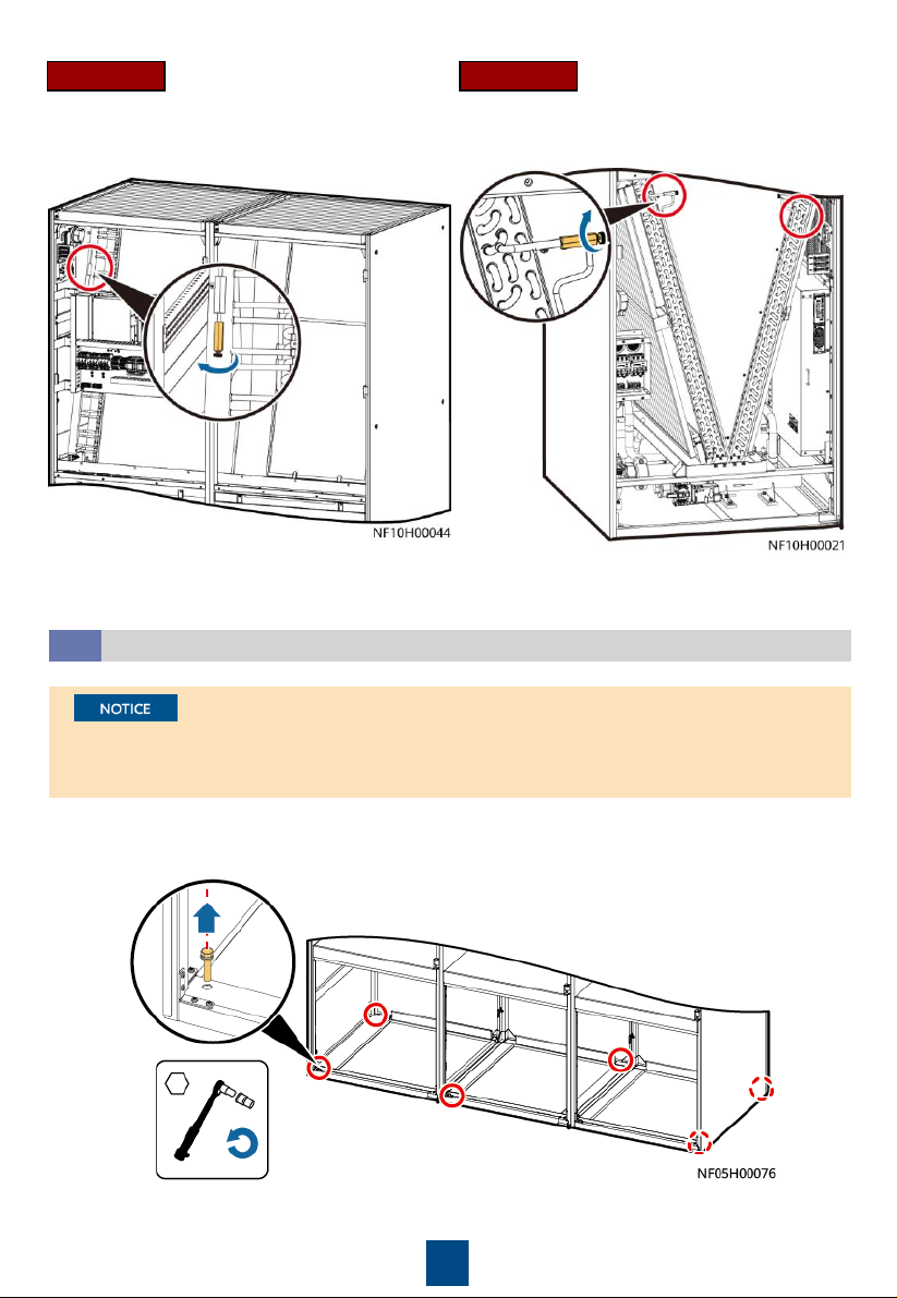
Open the front door and remove the rear door. Remove the bolts that secure the cabinet and
the pallet using a 19# socket wrench.
Removing the Pallet
3.2
1. For downflow units, remove the fan maintenance baffle plate at the front door before
removing the bolts.
2. For a single-door and double-dour cabinet, remove the four screws from both sides.
Downflow Upflow
4
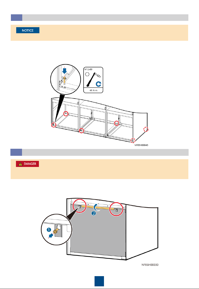
For a single-door and double-door cabinet, tighten the four screws on both sides.
Securing the Equipment
3.3
1. Secure the base to the ground using the six expansion bolts.
2. Move the cabinet onto the base. Secure the cabinet to the base using six bolts. Install a
shock pad between the base and the cabinet.
1. Exercise caution when raising or lowering a fan to prevent personal injury.
2. When removing the fan beam, assign one person to hold the fan.
Lowering a Fan (Applicable to Downflow Units)
3.4
a. Open the front door. Loosen the fan maintenance baffle plate and remove it from the
cabinet (using the left fan as an example).

5
b. Remove the six screws from the beams on both sides of the fan, and remove the two screws
on the connecting piece between the fan and the bottom of the cabinet. Remove the beams
and connecting piece.
c. At least two people are required to
rotate the fan. When the fan is 45
degrees to the bottom of the cabinet,
pull the fan along the guide rails on
both sides and rotate it inwards until
the fan is completely horizontal.
d. Place the fan support beam on the top of the
fan, and secure the fan support beam to the
cabinet by using screws, and secure the two
screws on the connecting piece. Connect the
fan signal cable and power cable to the
interconnection port reserved on the fan
panel, and bind the cables.
When removing the fan and connecting
piece between the fans and the bottom
plate, hold the fan to prevent it from
rotating automatically.
6
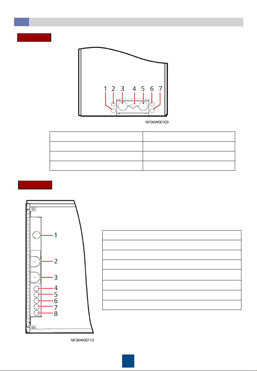
Hole Positions
3.5
(1) Drainpipe hole
(2) Signal cable hole
(3) Chilled water inlet pipe hole
(4) Humidifier water inlet pipe hole
(5) Chilled water outlet pipe hole
(6) Active power cable hole
(7) Standby power cable hole
(1) Drainpipe hole
(2) Chilled water inlet pipe hole
(3) Chilled water outlet pipe hole
(4) Humidifier water inlet pipe hole
(5) Pressure tube hole for the differential pressure sensor
(6) Signal cable hole
(7) Standby power cable hole
(8) Active power cable hole
Downflow
Upflow
7
Connecting Water Inlet and Outlet Pipelines
3.6
1. (Skip this step for upflow units.) Remove the baffle plate at the bottom of the cabinet, and
knock off the U-shaped hole in the baffle plate.
2. To avoid deforming the pipe, use a 75# open-end wrench to fix the pipe nut, use a 36#
open-end wrench to fix the plug, and then remove the plug.
3. Apply thread sealant evenly on the joints of external screw threads, and install the pipes
from inside out.
4. Use a 75# open-end wrench and an 18# pipe wrench to fix the pipes.
5. (Skip this step for upflow units.) Install the pipe baffle plate at the bottom of the cabinet,
and wrap the pipe and the baffle plate with thermal insulation foam.
1. Wrap thermal insulation foam around the whole pipes after pipes are connected.
2. Due to the hardening property of yellow adhesive, nitrogen injection and pressure preserve
should be operated 8 hours after the adapter is connected.
Downflow
Upflow
The figure uses side
pipe routing as an
example. If bottom pipe
routing is used,
purchase right angle
elbows with DN50
outer threads onsite.
8
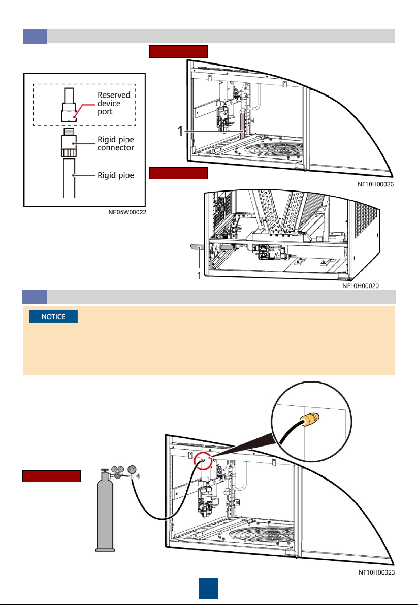
Connecting the Drainpipe
3.7
Upflow
Downflow
Connection method
(1) Drainpipe
(Optional) Leakage Test with Nitrogen
3.8
1. Rotate the chilled water valve to the maximum openness (100%).
2. Check that the needle valves and exhaust valves on the pipeline
are closed.
•If the pressure decreases, apply soapy water on the pipes, especially pipe joints to check for
any leakage.
•If the pressure is stable, wrap all pipes and connectors with thermal insulation foam.
•Install a reducing valve at the outlet of the nitrogen cylinder. The outlet pressure of the
reducing valve must be not more than 0.8 MPa.
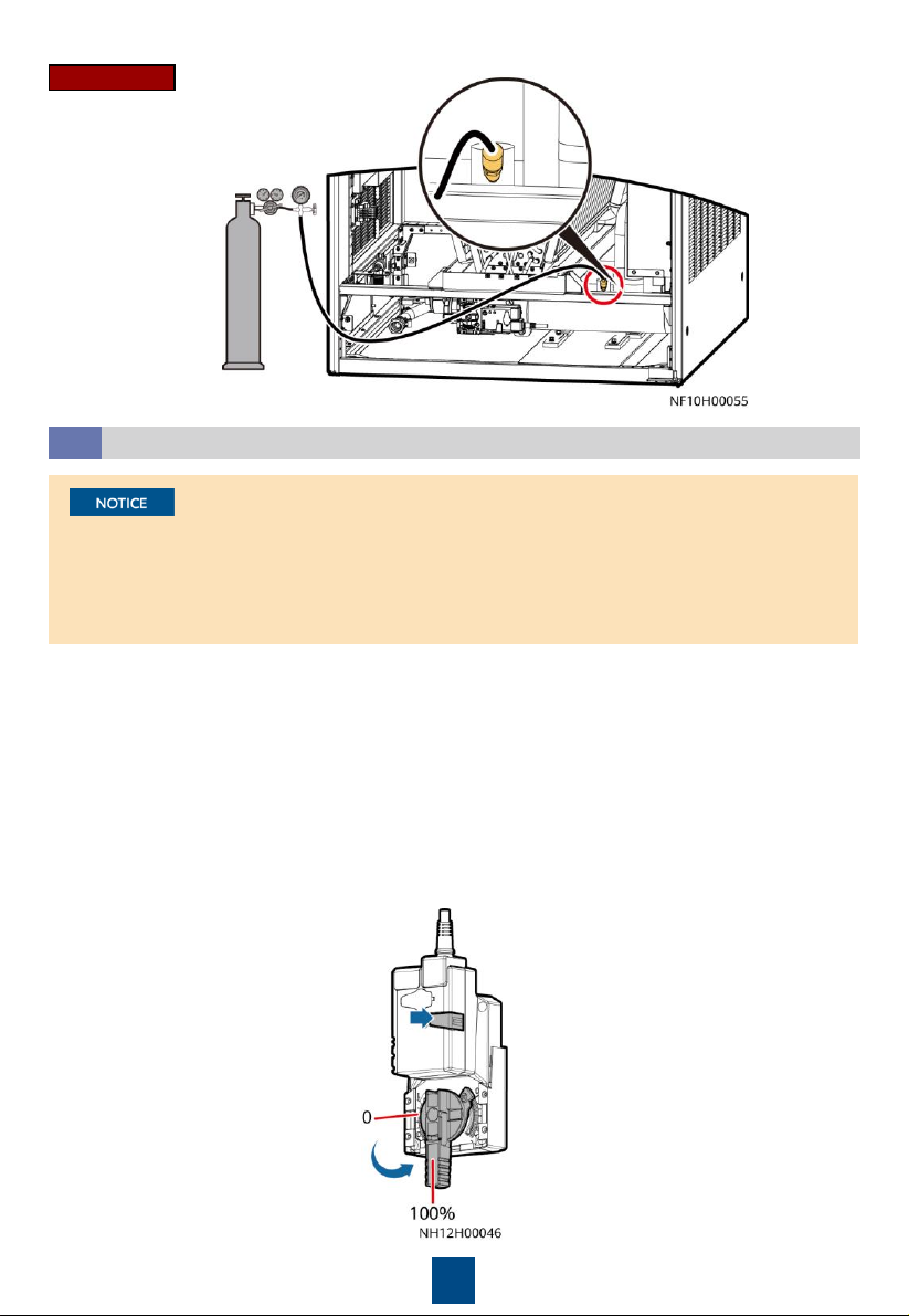
Downflow
(1) Drainpipe
4. Then, check that the pressure
reading on the pressure gauge
remains unchanged.
3. Connect the reducing valve and nitrogen cylinder to the
following needle valve, inject 0.8 MPa (when the pressure is
stable) nitrogen, and leave them for 24 hours.
9
1. Open the general water supply valve.
2. Verify that the chilled water valve is open (100%). If not, press the button on the side of the
actuator, and manually rotate the valve handle to the maximum.
3. Slowly open the exhaust valve to discharge air.
4. Adjust the air exhausting speed until no air flows out of the valve. Then close the exhaust
valve.
5. (If a leakage test with nitrogen has been performed, skip this step.) Raise the water pressure
in the chilled water pipe to 0.8 MPa. If no leakage occurs after 30 minutes, retain the
pressure for 24 hours. The expected result is that the pressure drop is less than 0.01 MPa and
the pipe does not leak.
6. Release the pressure in the pipes, and manually close the chilled water valve.
Leakage Test with Water
3.9
•To avoid blockage of the heat exchanger in the smart cooling product due to foreign
matter from the main pipe during the construction, you are advised to clean the main pipe
before water is supplied to the smart cooling product. Turn off the isolation valves on the
water inlet and outlet pipes before the cleaning and turn them on afterwards.
•Open the exhaust valve of each heat exchanger to exhaust nitrogen onsite.
Upflow
Other manuals for NetCol8000-C070
5
This manual suits for next models
2
Table of contents
Other Huawei Water Dispenser manuals


