Hitachi E-102SN3 User manual
1
ENGLISH
1
PMML0277A - rev.0 - 12/2012
INSTALLATION MANUAL FOR
MULTI-KITS
Line Branch Models:
E-102SN3, E-162SN3, E-242SN3, E-302SN3
NOTE
Hand over this installation manual to the next installation work
personnel.
1 APPLICABLE OUTDOOR UNITS
These multiple pipe connecting kits can be applied to the R410A
SET-FREE series.
2 TRANSPORTATION
Transport the product as close to the installation location as prac-
tical before unpacking.
CAUTION
Do not put any material on the product.
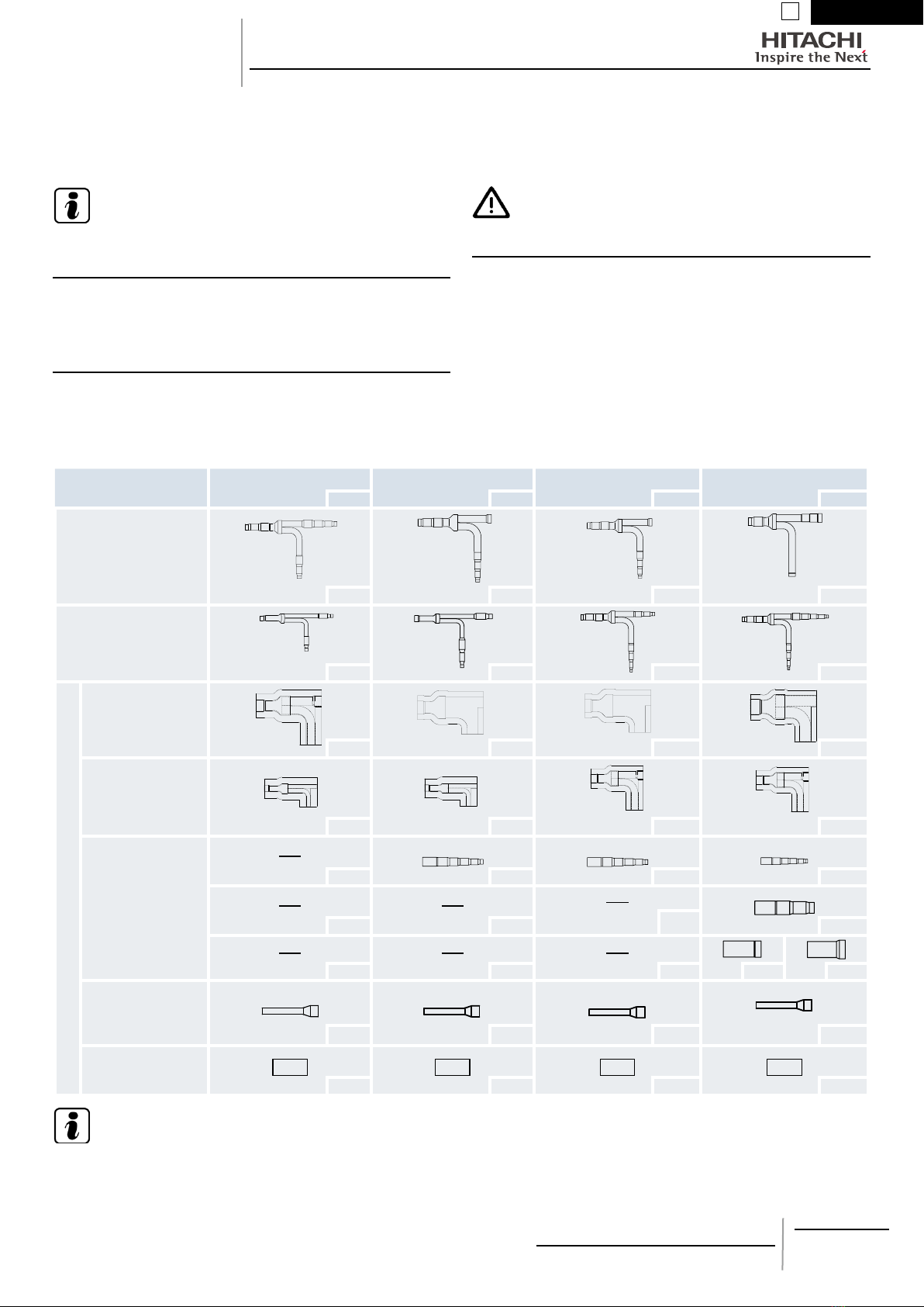
3 BEFORE INSTALLATION
Conrm the number of the following parts by referring to the mo-
del printed on the package before unpacking.
Do NOT put any foreign material into the parts. Check to conrm
that no foreign materials are inside the parts before installation.
Name of parts E-102SN3 E-162SN3 E-242SN3 E-302SN3
Q’ty Q’ty Q’ty Q’ty
Branch pipe for high/low
pressure gas line
1 1 1 1
Branch pipe for liquid line
1 1 1 1
Accessory
Insulation for high/low
pressure gas line
1 1 1 1
Insulation for liquid line
1 1 1 1
Reducer for high/
low pressure gas line
connection (For end of
Multi-Kit connection)
None 1 1 1
None
None None 1
None None None 1 1
Reducer for liquid line
connection (For unit
piping connection) 2 1 1 1
Tape
2 2 2 2
NOTE
If any of these parts is not contained, please contact your distributor.
2
PMML0277A - rev.0 - 12/2012
INSTALLATION MANUAL FOR
MULTI-KITS
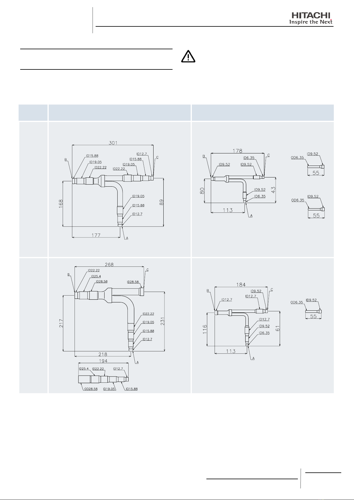
4 INSTALLATION WORK
4.1 PIPING CONNECTION SIZE
The ends of the multi-kits are nished as shown in the following
gures. Cut the end of the pipe to meet with the pipe size.
CAUTION
Piping shall be supported with adequate space. Bent pipes and
bypass piping (horizontal loop) shall also be installed in order to
absorb piping elasticity caused by temperature changes.
Model High/low pressure gas line Liquid line
E-102SN3
E-162SN3

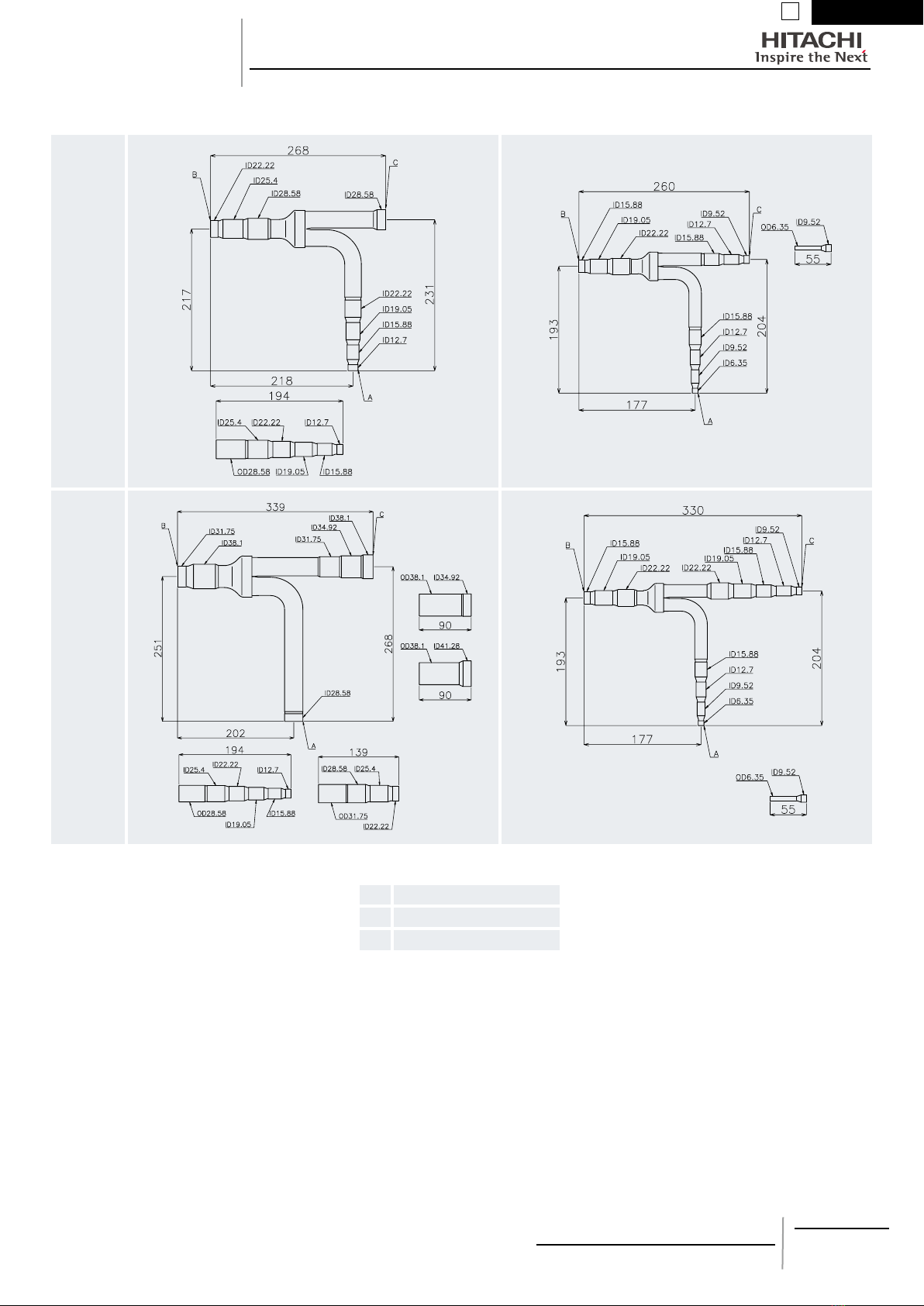
3
ENGLISH
1
PMML0277A - rev.0 - 12/2012
INSTALLATION MANUAL FOR
MULTI-KITS
Model High/low pressure gas line Liquid line
E-242SN3
E-302SN3
Unit: mm, ID: Inner Diameter, OD: Outer Diameter
A To indoor unit
B To outdoor unit
C To main piping

4
PMML0277A - rev.0 - 12/2012
4.2 INSTALLATION POSITION
1 Horizontal Installation
Locate the branch pipes to become the caution label uppermost on the same horizontal plane. (Inclination within +30o)
Make the straight length a minimum of 500mm after the vertical bend.
Straight length
500mm (Min.) Upward
INCORRET
Horizontally
Downward Inclination
within ±30º Inclination
(View from A)
2 Vertical Installation
Straight length of the pipe connection on the outdoor unit side is made as follows:
a. The collective pipe connection part is installed upward, the straight length must be min. 0.5m
b. The collective pipe connection part is installed downward, the straight length must be min. 0.3m.
Straight length
Min. 0.3m
Downward
Straight length
Min. 0.5m
Upward
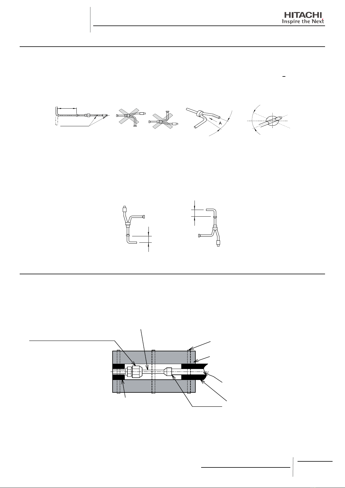
4.3 CONNECTION PROCEDURE FOR PIPING JOINT
When connecting liquid piping for the unit with a capacity 2.0HP or smaller, and with the length of piping is 15 meters or longer, apply
the piping size of f9.52mm. Fix the connecting pipe as shown in the below gure.
Use the insulation attached to the indoor unit.Example: 36HP (The combination of 3 outdoor units)
Field-Supplied insulation
Insulation attached to indoor unit
Field-Supplied refrigerant piping
Fix this part with the attached cord band
or eld-supplied vinyl tape.
Expander for liquid line (Accessory)
Flare the pipe after inserting the are nut.
Use the are nut of the indoor unit.
Insulate this part with the attached
insulation
Brazing
Indoor unit
INSTALLATION MANUAL FOR
MULTI-KITS
5
ENGLISH
1
PMML0277A - rev.0 - 12/2012
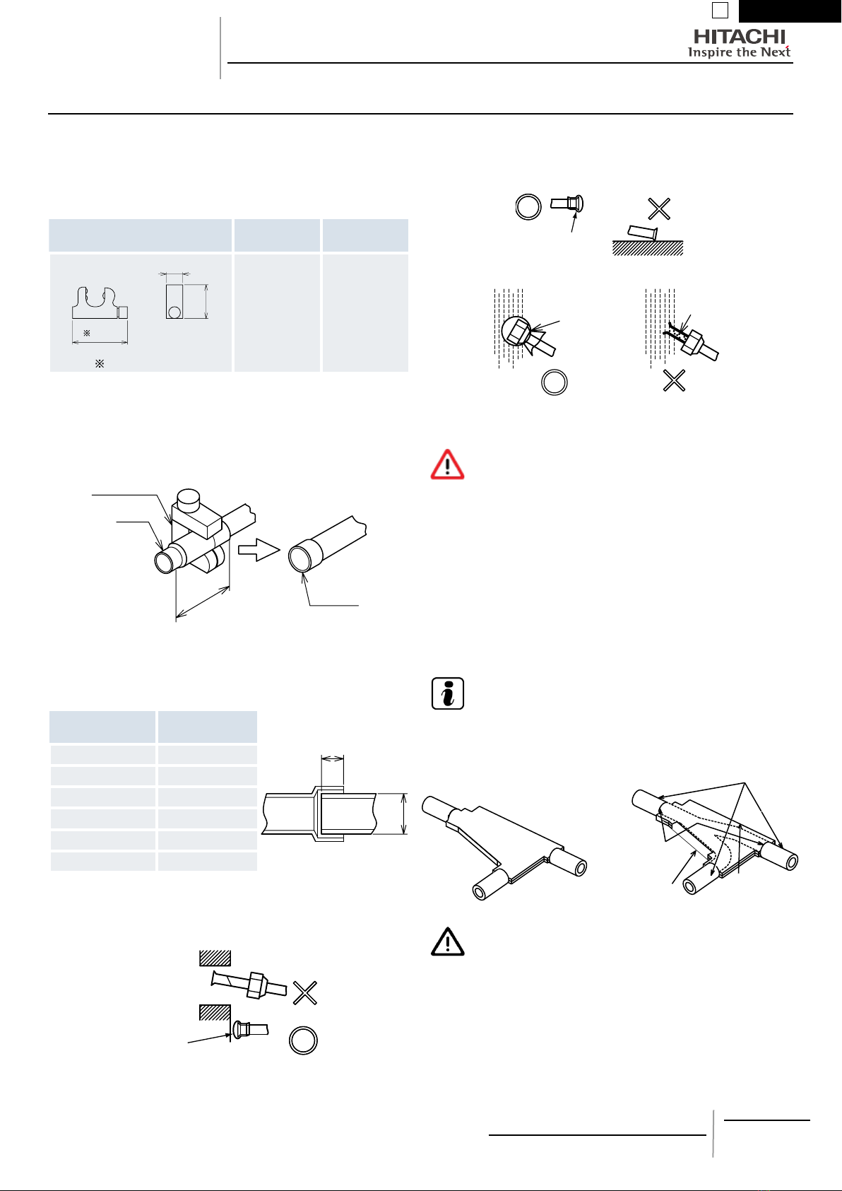
4.4 PIPING CONNECTION
INSTALLATION MANUAL FOR
MULTI-KITS
1 When the branched pipe size is smaller than 22.2mm of in-
ner diameter, a mini pipe cutter (eld-supplied) as follow is
required.
(mm)
Recommended mini pipe cutter Cleavable
size
Rotating
radius
(21)
(43)
(70)
less than 70mm
Ø5 - 28 (50)
2 Use clean copper pipes without any moisture or foreign mate-
rials on inner surface of pipes. When connecting refrigerant
pipe, cut the copper pipes with a pipe cutter as shown below.
Also blow the pipes with nitrogen or air to remain no dust insi-
de the pipe. Do NOT use a saw, a grindstone or others which
causes a large amount of cutting powder.
Pipe cutter
Pipe
Burring
Connection part
3 When cutting the pipe, secure the adequate depth for brazing
as shown in the following table.
(mm)
A: Outer diameter B: Minimum
depth
B
A
Over 5, Below 8 6
Over 8, Below 12 7
Over 12, Below 16 8
Over 16, Below 25 10
Over 25, Below 35 12
Over 35, Below 45 14
• Caution for Refrigerant Piping
When installing pipe through the wall, secure a cap at the end of
the pipe. INCORRECT
CORRECT
Attach a cap
or vinyl tape.
Hole
Do NOT place the pipe directly on the ground.
Attach a cap
or vinyl tape.
CORRECT INCORRECT
Attach a cap or
vinyl tape with
rubber band.
Rain water
can enter.
INCORRECT
CORRECT
4 Make sure that all stop valves of the outdoor unit are closed
completely.
5 Blow the inside of the pipes with nitrogen gas when brazing.
DANGER
Make sure that the refrigerant leakage test should be per-
formed. Refrigerant (Fluorocarbon) for the indoor unit is
non-ammable, non-toxic and odorless. However, if the re-
frigerant is leaked and is contacted with re, toxic gas will
generate. Also, because the uorocarbon is heavier than
air, the oor surface will be lled with it, which could cause
suffocation.
6 The air tight test pressure of this product is 4.15MPa.
7 Apply the insulation supplied with this multi-kits to each
branch (liquid side and gas side) with a tape. Also apply the
eld-supplied insulation to the eld-supplied pipes.
NOTE
When polyethylene foam is applied, a thickness of 10mm for li-
quid piping and 15mm to 20mm for gas piping is recommended.
(Use the insulation with heat resistance of 100oC for gas piping.)
Wrap the insultation tape without gap between
accessory insulation and eld-supplied insulation.
Insulation tape
(Field-Supplied)
Insulation for gas and
liquid line (Accessory)
Insulation (Field-Supplied)
Do NOT leave a
gap between the
insulation.
Fix the insulation with tape
(accessory) completely
after taping temporary.
CAUTION
• Perform the insulation work when the pipe surface tempera-
ture decreases to the room temperature. If insulation work
is performed immediately after brazing, insulation may melt.
• If the ends of pipe are open to the atmosphere for a while after
performing piping work, securely put caps or plastic bags over
the pipe ends for avoiding moisture or dust.
After installation, it is recommended to keep this manual by a
customer.


7
PMML0277A - rev.0 - 12/2012
ESPAÑOL
2
MANUAL DE INSTALACIÓN
DE KITS DE CONEXIONES
MÚLTIPLES
Modelos de distribuidor en línea:
E-102SN3, E-162SN3, E-242SN3, E-302SN3
N O TA
Facilite este manual al personal encargado de realizar la insta-
lación.
1 UNIDADESEXTERIORESAPLICABLES
Estos kits de conexiones múltiples pueden emplearse con la se-
rie SET-FREE R410A.
2 TRANSPORTE
Llevar el producto lo más cerca posible del lugar de instalación
antes de desembalarlo.
PRECAUCIÓN
No poner ningún material sobre el producto.
3 ANTES DE LA INSTALACIÓN
Antes de desembalar conrme las siguientes cantidades de pie-
zas consultando el modelo impreso en la caja.
NO coloque ningún material extraño en las piezas. Asegúrese de
que no hay ningún material extraño dentro de las piezas.
Nombre de las piezas E-102SN3 E-162SN3 E-242SN3 E-302SN3
Cant. Cant. Cant. Cant.
Tubería de bifurcación para
línea de gas de alta/baja
presión
1 1 1 1
Tubería de bifurcación para
línea de líquido
1 1 1 1
Accesorio
Aislamiento para línea
de gas de alta/baja
presión
1 1 1 1
Aislamiento para línea
de líquido
1 1 1 1
Reductor para la
conexión de línea de
gas de alta/baja presión
(para el extremo de la
conexión del
multi-kit)
Ninguno 1 1 1
Ninguno Ninguno Ninguno 1
Ninguno Ninguno Ninguno 1 1
Reductor para la
conexión de la linea de
líquido (para la co-
nexión de las tuberías
de la unidad) 2 1 1 1
Cinta
2 2 2 2
N O TA
Si falta cualquiera de estas piezas, póngase en contacto con su distribuidor.

8
PMML0277A - rev.0 - 12/2012
MANUAL DE INSTALACIÓN
DE KITS DE CONEXIONES
MÚLTIPLES
4 INSTALACIÓN
4.1 TAMAÑO DE LA CONEXIÓN DE LAS
TUBERÍAS
Los extremos de los kits de conexiones múltiples se muestran en
las guras siguientes. Corte el extremo de la tubería de acuerdo
con el tamaño de la misma.
PRECAUCIÓN
Las tuberías deben tener suciente espacio. Deben instalarse
también tuberías curvadas y de bifurcación (bucle horizontal)
para absorber la elasticidad causada por los cambios de tem-
peratura.
Modelo Línea de gas de alta/baja presión Línea de líquido
E-102SN3
E-162SN3
9
PMML0277A - rev.0 - 12/2012
ESPAÑOL
2
MANUAL DE INSTALACIÓN
DE KITS DE CONEXIONES
MÚLTIPLES
E-242SN3
E-302SN3
Unidad: mm, ID: diámetro interior, OD: diámetro exterior
A A la unidad interior
BA la unidad exterior
C A la tubería principal
10
PMML0277A - rev.0 - 12/2012
4.2 POSICIÓN DE LA INSTALACIÓN
1 Instalación horizontal
Identique la tubería de bifurcación donde irá la etiqueta de advertencia en el mismo plano horizontal. (Pendiente +30o)
Asegúrese de que la tubería está totalmente recta por lo menos durante 500 mm después de cada codo.
Tramo recto
500 mm (Mín.) Hacia arriba
INCORRECTO
Horizontal
Hacia abajo Inclinación ±30º Inclinación
(Vista desde A)
2 Instalación vertical
El tramo recto de la conexión de la tubería del lateral de la unidad exterior se realiza como se indica a continuación:
a. La pieza de conexión de la tubería colectiva se instala hacia arriba; el tramo recto debe tener un mínimo de 0,5 m.
b. La pieza de conexión de la tubería colectiva se instala hacia abajo; el tramo recto debe tener un mínimo de 0,3 m.
Longitud recta mín.
de 0,3 m
Hacia abajo
Longitud recta mín.
de 0,5m
Hacia arriba
4.3 PROCEDIMIENTO PARA LA CONEXIÓN DE LA JUNTA DE LA TUBERÍA
Al conectar tuberías de líquido de unidades de 2 CV o menos y de una longitud de 15 metros o más, utilice tuberías de f9,52 mm de
diámetro. Fije la tubería de conexión como se muestra a continuación.
Utilice el aislamiento en la unión con la unidad interior. Ejemplo: 36 CV (combinación de 3 unidades exteriores)
Aislamiento suministrado por el instalador
Aislamiento en la unión con la unidad
interior
Tubería de refrigerante suministrada por
el instalador
Sujete esta pieza con la abrazadera o con
cinta de vinilo suministrada por el instalador.
Extensor para la línea de líquido (accesorio)
Abocine la tubería después de insertar la tuerca cónica.
Utilice la tuerca cónica de la unidad interior
Aísle esta zona con el aislamiento
suministrado
Soldadura
Unidad
interior
MANUAL DE INSTALACIÓN
DE KITS DE CONEXIONES
MÚLTIPLES
This manual suits for next models
3
Table of contents
Languages:
Other Hitachi Air Conditioner Accessories manuals


Popular Air Conditioner Accessories manuals by other brands

Unitary products group
Unitary products group 2CE Series installation instructions

Qlima
Qlima EU-ODZ104 user manual

EMI
EMI 550000565 installation instructions

ActronAir
ActronAir MRE-035AS installation manual

Mitsubishi Electric
Mitsubishi Electric RCN-K-E installation manual

Tecnosystemi
Tecnosystemi smart clima INFINITY BLUE RIVER user manual


