HB Products HBLT User manual

Wire level sensor manual 05 October 2021 HBproducts.dk 1
Wire and Flex are intelligent liquid level sensors which can be installed in a vessel or in a standpipe. For the Wire sensor the
sensor element is a stainless steel wire insulated with PTFE and for the Flex sensor the element is a stainless steel wire
mounted with steel tube elements to increase the sensivity. Both sensors can to be mounted directly in a stand pipe. If they
need to be installed in a vessel they need an inner pipe. Both sensors measure between the wire/tube elements and the sur-
rounding pipe.
The sensor can be installed in refrigeraon systems and similar demanding applicaons with high pressures and aggressive
uids. The sensor emits a 4-20mA analog signal, which is proporonal to the liquid level.
The sensors comes in dierent versions with or without a cable for direct valve control. All versions emits a 4-20mA analog
signal, which is proporonal or disproporonal to the liquid level, via the M12 plug. The sensors are available in special ver-
sions which contains a controller able to control a valve directly, without using a PLC.
Introducon
Manual for wire level sensors delivered aer October 15th 2021*
Covers: HBLT & HBSLT
Wire sensor suited for liquids like NH3, and HFC/HFO refrigerants -not suited for water.
ATEX/Ex versions included
*Changes has been made to the sensor shipped from October
15th. The manufacturing date can be found on the silver label
on the electronic unit and it is the last 4 numbers in the V num-
ber in the format DDMMYY, The sensors can also be recog-
nized by the SW numbers:
73 or higher for RF3
32 or higher for RF4
The numbers are found at the top of the tool window when the
sensor is connected
Wire level sensor manual 05 October 2021 HBproducts.dk 2
Table of contents
Introducon...............................................................................................1
Safety Instrucons .....................................................................................2
Applicaon Examples..............................................................................3-5
Installaon Wire.........................................................................................6
Installaon Flex..........................................................................................7
Connecon diagrams............................................................................8-12
Analog output ..........................................................................................12
Use the HB-tool for seng up the sensor ..........................................13-16
LED indicaon ..........................................................................................17
Calibraon on the sensor.........................................................................17
Fault detecon.........................................................................................18
Sensor Repair...........................................................................................18
Further Informaon.................................................................................18
Safety Instrucons
CAUTION! Always read the instrucon manual before commencing work! Heed all warnings to the leer! Installaon of the
sensor requires technical knowledge of both refrigeraon and electronics. Only qualied personnel should work with the
product. The technician must be aware of the consequences of an improperly installed sensor and must be commied to
adhering to the applicable local legislaon.
If changes are made to type-approved equipment, this type approval becomes void. The product's input and output, as well
as its accessories, may only be connected as shown in this guide. HB Products assumes no responsibility for damages re-
sulng from not adhering to the above.
Explanaon of the symbol for safety instrucons. In this guide, the symbol below is used to point out important safety
instrucons for the user. It will always be found in places in the chapters where the informaon is relevant. The safety in-
strucons and the warnings in parcular, must always be read and adhered to.
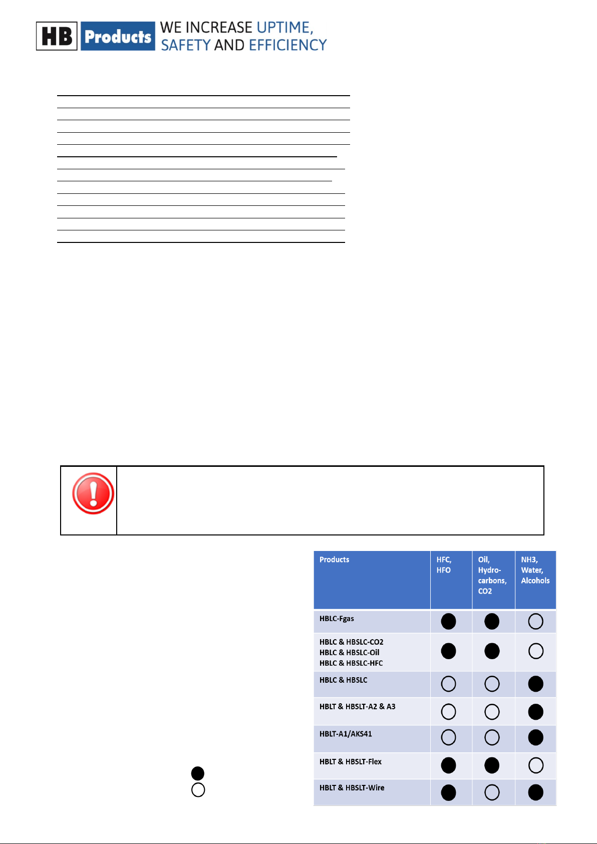
Intended use, condions of use. The level sensor is designed
for connuous measurement of liquids, but please note the
sensor design and setup has to comply with the liquid. The
table show how sensors comply to liquids. It can be used in
refrigeraon systems and similar environments. If the sensor
is to be used in a dierent way and if the operaon of the
product in this funcon is determined to be problemac,
prior approval must be obtained from HB Products.
Prevenon of collateral damage Make sure that qualied
personnel assess any errors and take necessary precauons
before aempng to make replacements or repairs, to avoid
collateral damage.
Disposal instrucons: The sensor is constructed so that the
modules can easily be removed and sorted for disposal.
CAUTION! Refers to a possible limitaon of funconality or risk in usage.
NOTE! Contains important informaon about the product and provides further ps.
The person responsible for operaon must commit to adhering to all the legislave requirements,
prevenng accidents, and doing everything to avoid damage to people and materials.
Comply
Not comply

Wire level sensor manual 05 October 2021 HBproducts.dk 3
Standpipe should be insula-
ted to avoid boiling in stand-
Drainpipe most be placed at
an angle of 5-10°, to avoid oil
pockets in standpipe.
Sensor must have a minimum
of 50 mm between the sen-
sor weight end and the
boom of the pipe.
The following applies to the design of the system:
• It must be installed in a vercal posion
• Sensor must have a minimum of 50 mm between the sensor weight end and the boom of the pipe.
• The sensor must be installed in an overow or standpipe where the ow stream and turbulence are minimized.
• The sensor must be mounted in a standpipe bigger than DN25. Standpipe must be insulated to avoid boiling of refrig-
erant.
• The outlet pipe from standpipe shall be mounted in an angle of 5-10 degree from horizontal to secure drainage and oil
pockets in refrigeraon systems.
• The sensor is installed and is supplied with a standard non-shielded cable.
If EMC is greater than described in EN 61326, a shielded cable must be used.
The wire sensor is designed for level measurement of liquids in vessels like,
tanks, pump separators and receivers . The sensor can be mounted in a
standpipe from 1” (25mm) up to 4” (100mm) diameter or directly in a vessel
with an inner pipe from 1” (25mm) up to 4” (100mm) diameter. The inner
pipe is needed to create sucient measuring signal and to avoid a swinging
wire in a lively uid. To reduce wire movements in larger pipes a special
weight can be used.
Installaon Instrucons—wire sensor
Special weight for mounng in turbulent
condions. The steel spacer “star” can be
shortened, using a simple n cung shear,
to t the standpipe. Allow 2 mm play be-
tween inner pipe diameter and “star” di-
ameter

Wire level sensor manual 05 October 2021 HBproducts.dk 4
Stand pipe: DN32..…DN65.
Recommended pipe standard: DIN 10220
Recommended bending: DIN 2615-1/Type 3
Recommended TEE: DIN 2615-1
Standpipe: DN65…DN100.
Recommended pipe standard: DIN 10220
Recommended bending: DIN 2615-1/Type 3
Site pipe can be designed in smaller pipe e.g. o.5 x DN.

Wire level sensor manual 05 October 2021 HBproducts.dk 5
Standpipe should be insula-
ted to avoid boiling in stand-
Drainpipe most be placed at
an angle of 5-10°, to avoid oil
pockets in standpipe.
Sensor must have a minimum
of 50 mm between the sen-
sor weight end and the
boom of the pipe.
The following applies to the design of the system:
• It must be installed in a vercal posion
• Sensor must have a minimum of 50 mm between the sensor weight end and the boom of the pipe.
• The sensor must be installed in an overow or standpipe where the ow stream and turbulence are minimized.
• The sensor must be mounted in a standpipe DN25 orDN32. The standpipe must be insulated to avoid boiling of refrig-
erant.
• The outlet pipe from standpipe shall be mounted in an angle of 5-10 degree from horizontal to secure drainage and oil
pockets in refrigeraon systems.
• The sensor is supplied and can be is installed with a standard non-shielded cable.
If EMC is greater than described in EN 61326, a shielded cable must be used.
The Flex sensor is designed for level measurement of liquids in
vessels like, tanks, pump separators and receivers . The sensor
can be mounted in a standpipe 1” (25mm) or 1 ¼” (32mm) diam-
eter or directly in a vessel with an inner pipe 1” (25mm) or 1
¼” (32mm) diameter. The inner pipe is needed to create su-
cient measuring signal and to avoid a swinging wire in a lively
uid.
Installaon Instrucons—Flex sensor

Wire level sensor manual 05 October 2021 HBproducts.dk 6
Wire adjustment—Wire sensor
The sensor is installed in the standpipe or directly in the tank. The sensor length is determined by standpipe length or tank
height. Cut the insulated steel wire to desired length with a wire cuers or bolt cuer in the end where the weight is in-
stalled. The weight is xed by the 2 screws. Liquid sealant is applied to the thread.
When sealing the conical thread, you must use liquid conducve sealant, which creates
a ground connecon between the standpipe/tank and the sensor, since the sensor uses
the standpipe/tank as reference. If Teon is used, it must only be used on part of the
thread so that the ground connecon is established. If you are in doubt regarding the
ground connecon, measuring the resistance between the tank and sensor is recom-
mended. This should be approx. 0 ohms.
An aluminum sealing/washer has been included for the sensor with cylindrical thread.
To install HBLT-wire, you must use a 2.5
mm Allen key, shiing spanner, and
gasket, depending on the type of
thread.
Separate the electronic part from the
mechanical part
Remove the insulaon 18 +/-2 mm
Dene the required length of sensor
from standpipe. Shorten the wire with
wire cuer.
Make sure that wire is in boom of
the hole.
Tighten the 2 set screws to x the wi-
re.Turn the top cover plasc part on
the metal part (right-hand thread)
L = Programmable sensor length
L= Wire length + 86 mm
Allow for 50 mm clearance below
the weight to the boom of the
tank—if relevant.
18

Wire level sensor manual 05 October 2021 HBproducts.dk 7
Installaon instrucon—Flex sensor
The sensor can be shortened to t the standpipe length or vessel height. The sensor consist of a 5 mm steel wire ed with
a stainless steel weight at the boom, plasc spacers and aluminum pipes. The purpose of the plasc spacers is to keep the
metal parts away from the pipe and the aluminum pipe increase the sensivity of the sensor.
The sensor length can be reduced to desired
length by reducing the wire length and removing
the aluminum pipes and spacers. Shorten the wire
by using a heavy wire cuer or bolt cuer in the
end where the weight is installed.
Allow for the wire to be inserted 25 mm into the
weight and a 50 mm clearance below the weight
to the boom of the vessel. You can have up to 50
mm free wire at the top or shorten one of the
aluminum pieces to get to the desired length.
When sealing the conical thread, you must use liquid conducve sealant, which cre-
ates a ground connecon between the standpipe/tank and the sensor, since the sen-
sor uses the standpipe/tank as reference. If Teon is used, it must only be used on
part of the thread so that the ground connecon is established. If you are in doubt
regarding the ground connecon, measuring the resistance between the tank and
sensor is recommended. This should be approx. 0 ohms.
An aluminum sealing/washer has been included for the sensor with cylindrical thread.
The sensor with all elements removed from the wire. To shorten HBSLT/HBLT-Flex, you only need
to remove the necessary elements. A large wire cuer is needed for the wire.

Wire level sensor manual 05 October 2021 HBproducts.dk 8
+24V DC or AC
- Common
DO, Alarm output
AO, 4-20 mA level
Communicaon only
1
5
4
3
2
PLC
+
-
DI
AI
DO
Connecon diagram for sensors without control
cable. With and without temperature compensa-
on
Suited for
• HBLT and HBLT-wire & Flex
• HBLC
How to connect the sensor
Two dierent type of sensors
• A pure sensor version with 4-20 mA output
• A controller version with both cable for direct valve control and analog output
All sensors can provide a signal for a PLC via the M12 connection. The M12 connection is also used for power supply.
Some versions are able to control a valve directly. They have a cable, which can be connected directly to the valve.
PLC
Controller and
sensor version
HBSLT
HBSLC
PLC (oponal)
or
Power supply
Sensor only version
• HBLT
• HBLC
Digital output on pin 3
The sensor versions without a cable has an alarm out-
put on pin 3. Remote setpoint is not available

Wire level sensor manual 05 October 2021 HBproducts.dk 9
+24V DC or AC
- Common
AI Remote set point 4-20 mA
AO, 4-20 mA level
Run in signal
1
5
4
3
2
PLC
+
-
AO
AI
DO
Color coding
A+ = yellow(2)
A- = white (4)
B- = green (1)
B+= brown (3)
The sensor has a build in controller for a stepper valve. The sensor pro-
vides both the analog output via the cable to control the valve. The lev-
el measurement signal for the PLC comes via the M12 plug .
On pin 3 it is possible to send an analog 4-20 mA signal to the controller
and change the setpoint. The signal is scaled linear like analog output.
The cable is connected according to the drawing and the parameters
are set as shown in the next secon.
For the stepper motor setup a
special menu is acvated
Connecon diagram for sensors with control ca-
ble for all common stepper motor valves — here
shown with Carel E2V
Suited for
• HBSLT/S and HBSLT–wire & Flex/S
• HBSLC/S

Wire level sensor manual 05 October 2021 HBproducts.dk 10
+24V DC or AC
- Common
AI Remote set point 4-20 mA
AO, 4-20 mA level
Run in signal
1
5
4
3
2
PLC
+
-
AO
AI
DO
Connecon diagram for sensors with control ca-
ble for pulse modulang valve — here shown
with Danfoss AKV/AKVA
The sensor has a build in controller for a pulse modulang valve. The
sensor provides both the analog output via the cable to control the
valve. The level measurement signal for the PLC comes via the M12
plug .
On pin 3 it is possible to send an analog 4-20 mA signal to the controller
and change the setpoint. The signal is scaled linear like analog output.
The cable is connected according to the drawing and the parameters
are set as shown in the next secon.
Suited for
• HBSLT/PWM and HBSLT–wire & Flex/
PWM
• HBSLC/PWM
Wiring using cable
Brown: + when using DC
White: - common when using DC
The cable can supply AC as well
This manual suits for next models
13
Table of contents
Other HB Products Accessories manuals

HB Products
HB Products HBDF MK2 User manual

HB Products
HB Products HBLC User manual

HB Products
HB Products HBCP User manual

HB Products
HB Products HBOC User manual

HB Products
HB Products HBDF User manual

HB Products
HB Products SLCD-M1/_Ex Series User manual

HB Products
HB Products HBIB Use and care manual

HB Products
HB Products HBLC Series User manual

HB Products
HB Products HBLT-A1 User manual

HB Products
HB Products HBPH-MK2 User manual


