Halton Capture Ray KVE-UV User manual

Operators Manual
for Capture Ray®(UV)
Manual provides
Operation, Maintenance and Service Instructions
Form#: OM010_CAPTURE RAY (UV)
Date: July 2017 - Rev4
Capture Ray® Hoods with UV Technology
KVE-UV, KVC-UV, KVL-UV, KVW-UV

2
Capture Ray®UV Operation & Maintenance Manual
OM-010/072017/rev4/EN
GENERAL DESCRIPTION
Halton’s Capture Ray®technology provides solutions for a variety of commercial food service venti-
lation applications over virtually any cooking process. Based on Halton’s patented highly efficiency
Capture Jet®solution and advanced mechanical KSA filter technology, the Capture Ray®(UV) feature
keeps the plenum and duct virtually grease free and mitigates the cooking odor and emissions. The
integrated Capture Ray®Ultraviolet cassette(s) are positioned in the exhaust plenum of the hood
behind the mechanical grease filters. The grease vapor and effluents that are not collected by these
high-efficiency mechanical filters pass over the UV lamps. This causes a chemical reaction within the
grease molecules that destroys the grease and converts it into carbon dioxide and water vapor. The
chemical action carries over into the exhaust duct and helps keep the duct and exhaust fan clean.
The UV system is built into the hood with complete controls and safety features which prevent ex-
posure to the UV light.
The hood is complete with a control panel indicating the total hours of operation, safety alarms,
security on, and exhaust fan failure. There are two sizes of UV cassettes: one short, which is
(234W) 38” long, one long, which is (390W) 66” long. These cassettes are matched to the overall
length of the hood in various combinations to provide maximum grease destroying capability for the
hood. The UV control panel is suitable for a single phase power supply and is constructed to meet
the UL listed protection standard.
The cassette access plate includes a hinged door for ease of maintenance and replacement of the
UV bulbs. The cassettes are mounted on a rack and are easily removed by disconnecting the
electrical connectors on the cassettes end. The UV cassette access door comes equipped with
safety switches. If the door is not secured in the closed position, the system will not operate. The
control panel is connected to the electrical control box of the fan via a relay which detects any
exhaust fan failures. The UV system will not operate if the exhaust fan does not work
To achieve the optimum performance from your hood system (s) please use the following guidelines
provided within the pages of this Installation, Operation, and Maintenance Manual.
In addition to this information our offices or local representatives are available at any time to
provide additional technical support for products, applications, installation, commissioning or in any
aspect that you may have.
RECOMMENDATION
Upon receipt of the Halton hood (s), inspect unit (s) immediately for any shipping damage and notify
carrier immediately if damage is found. Halton will not accept responsibility for any shipping damage.
All systems are thoroughly inspected before leaving our factories; however Halton will assist in filing
a claim if needed.
GENERAL INSTALLATION
It is the responsibility of the installing contractor to see that the system installation is completed in ac-
cordance with the project plans and specifications and that it meets all specific requirements of local
code officials. The local authority having jurisdiction could over rule some of the installation details
written in this manual. The installation shall be in accordance with NFPA-96. All electrical systems
shall be installed following local and national codes.

3
Capture Ray®UV Operation & Maintenance Manual
OM-010/072017/rev4/EN
The owner and/or operator should be instructed in the proper operation, care and maintenance of the
system.
If questions or complications should arise during the installation of the Halton hood (s) that cannot
be solved using the instructions provided please contact the Halton office at 1-800-442-5866, or
(1-800-4-HALTON).
Note: There are no instructions contained within this manual for installation or maintenance of fan
packages.
**See appropriate manufacturers manual for detailed instructions.
EXHAUST AIRFLOWS
Please see submittal drawings or contact the manufacturer for each hood’s exhaust air flow rates.
Halton’s applications department determines the optimum exhaust rate for effective capture &
containment of cooking effluent. These exhaust airflows are included in the job submittal drawings
for each hood and are customized for the specific kitchen appliance arrangement and environment.
INSTALLATION INSTRUCTIONS
1. Inspect the crating carefully. If there are signs of damage, call the freight carrier before
uncrating the units. Carefully uncrate the units. Check all local codes prior to installation; special
requirements may be necessary depending on local building material construction.
** Important note ** Do not leave unit (s) exposed to extreme temperatures for an extended
period of time, this may cause the protective PVC coating around the unit (s) to become very
difficult to remove.
2. Position the hood near the actual installation site. In case of multiple hoods, check the
engineered set of drawings for locations. Pay close attention to collar sizes and fire
protection layouts, matching the hood systems to the correct location shown on the
drawings provided.
**Check item numbers on crates / hoods vs. drawing item numbers.
3. Once the hood is carefully removed from the shipping crate and set in position, the unit is
now ready for installation. If Halton Company has supplied a backsplash assembly, then
the splash assembly should be installed first, for installation procedures see pg. 3.
4. Hang the hood using ½” threaded rods by attaching the rods to the hood through the hanger
brackets that are welded to the top of the hood. Use of turnbuckles with the threaded rod
sections will make final adjustment easier. Standard hanging height for canopy hoods ranges
from 78” min. to 84” max. from the finished floor to the lower edge of the front of the hood (per
local codes having jurisdiction). **Noted in installation instructions - see pg. 3.

4
Capture Ray®UV Operation & Maintenance Manual
OM-010/072017/rev4/EN
Note:
Allow 100lbs (45kg) per linear foot hanging weight.
Do not lift exhaust hoods from their end panels. Lift from four corners.
All exhaust hoods and control panels are fitted together and factory tested prior to shipping for
alignment and operation.
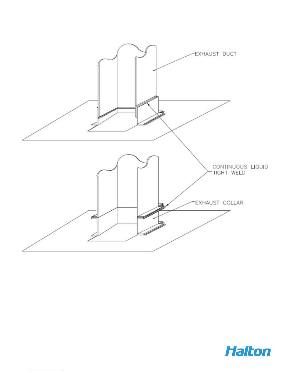
5. Duct connections must meet NFPA 96 requirements and applicable local codes. Size of
connection is indicated on exhaust hood drawing. Connection is to be made after exhaust hood
is hung.
6. Electrical circuits should be connected according to the standard switch panel wiring diagram.
UV hoods have additional wiring requirements to connect the control panel to the hoods, as well
as connections between multiple hoods operated from the same control panel. The following
electrical service requirements are field installed:
A 120 volt, 15 amp uninterrupted supply to the control panel.
A 120 volt circuit from the control panel to the exhaust fan starter coil or relay.
A 120 volt circuit from the control panel to the make up air fan starter coil or relay.
A separate 120 volt, 15 amp supply to the light fixture junction box(es) on top of each hood.
Note: The selector switch on the control panel controls the exhaust fan operation.
Please see job specific wiring connection information in the job submittal drawings and an
additional wiring diagram is included in the electrical control box shipped with the job. Additional
copies may be obtained from the factory if this wiring diagram is missing or lost. Please be
prepared to provide the job order number (found on the sales invoice), job name and address
or submittal drawing series number when contacting the factory for this or other job specific
documents.
7. Grease filters and grease cups must be installed in place before start-up.
8. Halton hood come standard with high output, long lasting LED light fixtures. Optionally
incandescent or recessed fluorescent fixtures may be ordered. Please note only install 100 watt
maximum light bulbs in incandescent light fixtures. Fluorescent bulbs should be type T8, 36”
or 48” long in fluorescent fixtures. **Note: Halton does not provide bulbs for incandescent or
fluorescent lights.
9. If Closure Panels are supplied by Halton see pg. 9 for details on the installation.
10. For multiple hoods end to end, or back to back see pg. 8 for Installation of Splice Strips and
U-Channels.
11. Protect the hood from damage under normal job site conditions, until all work is complete and
system is ready to be put into operation.

5
Capture Ray®UV Operation & Maintenance Manual
OM-010/072017/rev4/EN
BACKSPLASH INSTALLATION

6
Capture Ray®UV Operation & Maintenance Manual
OM-010/072017/rev4/EN
HOOD INSTALLATION DETAILS

7
Capture Ray®UV Operation & Maintenance Manual
OM-010/072017/rev4/EN
EXHAUST DUCT CONNECTION DETAILS

8
Capture Ray®UV Operation & Maintenance Manual
OM-010/072017/rev4/EN
SPLICE STRIP/U-CHANNEL ASSEMBLIES

9
Capture Ray®UV Operation & Maintenance Manual
OM-010/072017/rev4/EN
CLOSURE PANEL ASSEMBLY - SINGLE HOOD

10
Capture Ray®UV Operation & Maintenance Manual
OM-010/072017/rev4/EN
CLOSURE PANEL ASSEMBLY - END TO END HOODS
This manual suits for next models
3
Table of contents
Other Halton Ventilation Hood manuals

Halton
Halton KVE-UV User manual

Halton
Halton Capture Jet KVESJ User manual

Halton
Halton M.A.R.V.E.L. User manual

Halton
Halton MM1 Series User manual

Halton
Halton EcoloAir 3000CFM User manual

Halton
Halton MM1 Series User manual

Halton
Halton Rex Expander Product manual

Halton
Halton Capture Jet KVE-WW User manual

Halton
Halton KVE (SJ-SK) User manual

Halton
Halton KVF Capture Jet Instruction Manual