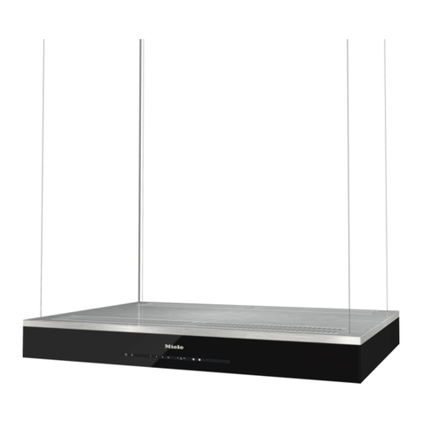
Häfele 533.89.001 User manual

INSTRUCTION
MANUAL
EnglishVietnamese
PRODUCTS NAME: COOKER HOOD
Products Applied: 533.89.001, 533.89.003, 533.89.031

2
INDEX
1. SAFETY INFORMATION
2. CHARACTERISTICS
3. INSTALLATION
4. USE
5. CARE AND CLEANING
COOKER HOOD

3
1. SAFETY INFORMATION
For your safety and correctoperation of the appliance, read this manual
carefully before installation and use. Always keep these instructions with the
appliance even if you move or sell it. Users must fully know the operation
and safety features of the appliance.
The wire connection has to be done by specialized technician.
The manufacturer will not be held liable for any damages resulting from
incorrect or improper installation.
•The minimum safety distance between the cooker top and the e
hood is 650 mm (some models can be installed at a lower height,
refer to the paragraphs on working dimensions and installation).
•If the instructions for installation for the gas hob specify a greater
this must be respected.
•Check that the mains voltage corresponds to that indicated on the
plate fixed to the inside of the hood.
Means for disconnection must be incorporated in the fixed wiring in
accordance with the wiring rules.
For Class I appliances, check that the domestic power supply
adequate earthing.
•Connect the extractor to the exhaust flue through a pipe of minimum
diameter 120 mm. The route of the flue must be as short as possible.
•Regulations concerning the discharge of air have to be fulfilled.
•Do not connect the extractor hood to exhaust ducts carrying
fumes (boilers, fireplaces, etc.).
•If the extractor is used inconjunction with non-electrical appliances (e.g.
burning appliances), a sufficient degree of aeration must be guaranteed
the room in order to prevent the backflow of exhaust gas. When the cook
hood is used in conjunction with appliances supplied with energy other
electric, the negative pressure in the room must not exceed 0,04 mbar
prevent fumes being drawn back into the room by the cooker hood.

4
•The air must not be discharged into a flue that is used for exhausting
from appliances burning gas or other fuels.
•If the supply cord is damaged, it must be replaced from the manufacturer
its service agent.
•Connect the plug to a socket complying with current regula tions, located
an accessible place.
With regards to the technical and safety measures to be adopted for
discharging it is important to closely follow the regulations
provided by the local authorities.
Use only screws and small parts in support of the hood.
WARNING: Before installing the Hood, remove the protective films.
Accessible parts may • become hot when used with cooking appliances.
WARNING: Failure to install the screws or fixing device in accordance with
these instructions may result in electrical hazards.
•Do not look directly at the light through optical devices (binocuIars,
glasses ... ).
Do not flambe under the range hood; risk of fire.
•This appliance can be used by children aged from 8 years and above
persons with reduced physical, sensory or mental capabilities or lack of
experience and knowledge if they have been given supervision or instr
concerning use of the appliance in a safe way and understand the
involved. Children shall not play with the appliance. Cleaning and user mainte-
nance shall not be made by children without supervision.
•Children should be supervised to ensure that they do not play with the
appliance.
•The appliance is not to be used by persons (including children) with
physical, sensory or mental capabilities, or lack of experience and
unless they have been given supervision or instruction.
•Clean and/or replace the Filters after the specified time period (Fire
See paragraph Care and Cleaning.

5
There shall be adequate ventilation of the room when the range hood is used
at the same time as appliances burning gas or other fuels (not applicable to
appliances that only discharge the air back into the room).
•The symbol on the product or on its packaging indicates that this
may not be treated as household waste. Instead it shall be handed over to
applicable collection point for the recycling of electrical and electronic equip-
ment. By ensuring this product is disposed of correctly, you will help
potential negative consequences for the environment and human health,
could otherwise be caused by inappropriate waste handling of this
For more detailed information about recycling of this product, please
your local city office, your household waste disposal service or the shop
you purchased the product.
“In case of replacement with halogen lamp use only self-shielded
tungsten halogen lamps or self-shielded metal halide lamps.”

6
2. CHARACTERISTICS
Ref. Q.ty Product Components
11 Hood Body, complete with: Controls,
Light, Blower, Filters
81 Directional Air Outlet grille
91Reducer Flange Ø 150-120 mm
20 1 Closing element
Ref. Q.ty Installation Components
12a 4Screws 4,2 x 44,4
12b 2Screws 4,2 x 12,7
12e 2Screws 2,9 x 12,7
Q.ty Doc1mentation
1 Instruction Manual
Components
Min.
500mm
Min.
650mm
12b

7
3. INSTALLATION
Drilling the Support surface and Fitting the Hood
Connections
SCREW FITTING
CLOSING ELEMENT
DUCTED VERSION AIR EXHAUST SYSTEM
•The hood support surface must be 135 mm above
bottom surface of the wall units.
•Drill the support with a Ø4,5 mm drill bit, using
drilling template provided.
•Cut a hole Ø 150 mm in size on the support sur
using the drilling template provided.
•Fix using the 4 screws 12a (4,2 x 44,4) provided.
The space between the edge of the hood and the
rear wall can be closed by applying the element
20 provided, using the screws 12b.
•To install a Ø 120 mm air exhaust connection, in-
sert the reducer flange 9 on the hood body outlet.
•Fix the pipe in position using sufficient pipe
(not supplied).
•Remove possible charcoal filters.
When installing the ducted version, connect the
hood to the chimney using either a flexible or rigid
pipe Ø 150 or 120 mm, the choice of which is left
to the installer.
12a
135
150
20
12b
ø 150
9
ø 120

8
RECIRCULATION VERSION AIR OUTLET
ELECTRICAL CONNECTION
•Cut a hole Ø 125 mm in any shelf that
be positioned over the hood.
•Insert the reducer flange 9 on the
body outlet.
•Connect the flange to the outlet on the
over the hood by using a flexible or
pipe Ø 120 mm.
•Fix the pipe in position using
sufficient pipe clamps (not supplied).
Fix the air outlet grid 8 on the
air outlet by using the 2 screws 12e
x 9,5) provided. Ensure that the
charcoal filters have been inserted.
•Connect the hood to the mains through a two-pole switch having a contact gap of
least 3 mm.
•When opening the sliding carriage for the first time after installing the hood, pull it
briskly until it clicks.
88
9
9
125125
12e

9
4. USE
Control panel
L Light L Light
M Motor M Motor
V Speed V Speed
Switches the lighting
system on and off.
Switches the extractor
motor on and off.
Sets the operating
speed of the extractor:
Switches the lighting
system on and off.
Switches the extractor
motor on and off.
Sets the operating
speed of the extractor:
1. Low speed, used for
a continuous and silent
air change in the pres-
ence of light cooking
vapour.
2. Medium speed, suit-
able for most operating
conditions given the
optimum treated air
flow /noise level ratio.
3. Maximum speed,
used for eliminating the
highest cooking vapour
emission, including
long periods.
1 . Low speed, used for
a continuous and silent
air change in the pres-
ence of light cooking
vapour.
2. Medium speed, suit-
able for most operating
conditions given the
optimum treated air
flow/noise level ratio.
L
M - V
0
1
0
1
2
3
L
M-V

10
5. CARE AND CLEANING
Grease filters
Charcoal filter (Recycling version)
CLEANING METAL CASSETTE GREASE
FILTERS
REPLACING CHARCOAL FILTERS
•The fillers must be cleaned every 2 months, or
frequently in case of particularly heavy use
hood. Filters can be washed in a dishwasher.
•Pull out the sliding suction panel.
•Remove the filters one by one, after having discon-
nected the relative fastening elements.
•Wash the filters, taking care not to bend them.
them get dry before refitting them. (The colour of
filter surface may change throughout the time but
has no influence to the filter efficiency).
•When refitting the filters, make sure that the handle
visible on the outside.
•Close the sliding suction panel.
•These filters are not washable and cannot be regener-
ated, and must be replaced approximately every
months or more frequently by particularly heavy use.
•Pull out the sliding suction panel.
•Remove the grease filters.
•Remove the saturated carbon filter by releasing
fixing hooks
•Fit the new filter by hooking it into its seating.
•Replace the grease filters.
•Close the sliding suction panel.
Warning: Turn the lights off and wait until the lamps cool
down before you change the odour filter.
This manual suits for next models
2
Table of contents
Languages:
Other Häfele Ventilation Hood manuals

Häfele
Häfele 495.38.283 User manual

Häfele
Häfele HH-WI70B Technical manual

Häfele
Häfele 533.86.003 User manual

Häfele
Häfele HH-IG90B Technical manual

Häfele
Häfele HH-ST60 User manual

Häfele
Häfele HH-WVG90A User manual

Häfele
Häfele HH-BI72A User manual

Häfele
Häfele Telescopic Hood HH-TT70A User manual

Häfele
Häfele 533.89.013 User manual

Häfele
Häfele HH-WVGS90A User manual