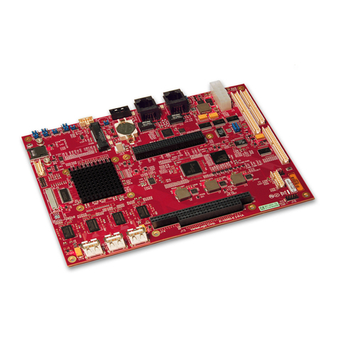
Giantec GT-650 User manual

GT-650
Pentium III/Celeron
w/VGA/LAN/Audio
w/Video Capture/GPIO
Embedded Board
User’s Manual

User’s Manual
GT-650 i
@ Copyright 2002
All Right Reserved
The information in this document is subject to change without prior notice in order
to improve reliability, design and function and does not represent commitment on
the part of the manufacturer.
In no event will the manufacturer be liable for direct, indirect, special, incidental, or
consequential damages arising out of the use or the possibility of such damages.
This document contains proprietary information protected by copyright. All rights
are reserved. No part of this manual may be reproduced by any mechanical,
electronic, or other means in any formwithout prior written permission of the
manufacturer.
Acknowledgments
All trademarks and registered trademarks mentioned herein are the property of their
respective owners.
Nov. 2002
Printed in Taiwan
Version A

User’s Manual
GT-650 ii
Check List
Before getting started, please check if your GT-650 package includes the following
items:
lGT-650 PentiumIII/Celeron Embedded board x 1pcs
lDriver & Utility CD_ROM x 1 pcs
lHDD cable x 1 pcs
lUser’s manual x 1pcs
lAD-011 8 ports Video input / GPIO adapter card, cable x 1pcs

User’s Manual
GT-650 iii
Table of Contents
Chapter 1. Introduction
1.1 General Introduction…………………………………….1-1
1.2 Specifications…………………………………………… 1-2
Chapter 2. Jumpers and Connectors
2.1 Jumpers setting ………………………………….……… 2-2
2.2 Connectors …………………………………….……….. 2-4
Chapter 3. Installation.
3.1 Installing the DIMMs ……………………..………….. 3-1
3.2 Installing the CPU ……………………………….…… 3-2
3.3 Completing the Installation ………………….……….. 3-3
Chapter 4. AWARD BIOS Setup
4.1 Introduction …………………………………..……….4-1
4.2 The Main Menu ……………………………………… 4-4
4.3 Standard CMOS Setup …………………………….….4-6
4.4 Advanced BIOS Features …………………………….4-10
4.5 Advanced Chipset Features …………………………..… 4-13
4.6 Integrated Peripherals ..…………………………..…... 4-16
4.7 Power Management Setup ………………..…………….4-20
4.8 PnP/PCI Configuration setup………………………..….4-23
4.9 PC Health Status ……………………………………….. 4-25
4.10 Default Menu ………………………………………… 4-27
4.11 Password Setting……………………………………….. 4-28
4.12 Exit Selecting ………….. ………..…………………….. 4-29
4.13 POST Messages ……………………………………… 4-30
4.14 POST codes ………………………………………….…4-36
Chapter 5. Software Setup
5.1 INF update utility for 815E chipset ……..…………….5-1
5.2 Intel 815E chipset Graphics control Driver .………….5-6
5.3 PCI Multimedia Audio Device ………………….……… 5-8
5.4 PCI Ethernet Controller Found ………………………….5-13
5.5 PCI Multimedia Video Device Found ………………….. 5-29
Appendix A. Network
Appendix B. Connectors’Pin Assignment
Appendix C. Updating BIOS
Appendix D. WatchDog Timer
Appendix E. Mechanical Drawing

User’s Manual
GT-650 Introduction 1 - 1
- 1 -AAAAAAA
Chapter 1
Introduction
This manual describes the GT-650 single board computers. Chapter 1provides
general information and specifications. Chapter 2contains jumper and
connector information. Chapter 3describes component installations. Chapter 4
describes AWARD BIOS setup information and BIOS POSTcode, and Chapter 5
for software setup procedure. Appendix Adescribes the network interface.
Appendix Blists the connector pin assignment. Appendix Cdescribes the
updating the systemBIOS. Appendix D for the mechanical drawing
1.2 General introduction
The GT-650 is afull featured, industrialized, single board computer with a
high-frequency Intel Tualatin, PentiumIII®, and Celeron®processor that brings
advanced CPU technology and processing power to the latest PCI applications.
The INTEL 815E AGP chipset built in to the single board computer is the most
efficient and reliable way to upgrade existing ISA systemsto PentiumIII
technology.
The GT-650 combines many features needed for system operation into one
compact single board computer,including 2D/3D graphics accelerator,10/100
TX Ethernet adapter,Two USB ports, Two Ultra/DMA IDE drive controllers,
Two high performance serial ports, enhanced parallel port, and the latest BIOS
features. Additional enhancements to the GT-688V include asixteen-channel
maximumvideo input interface. Two dual in-line memory module (DIMM)
sockets support up to 512MB of synchronous DRAM (SDRAM) memory.
The INTEL 815E includes ahighly integrated graphics accelerator.Its
architecture consists of dedicated multi-media engines executing in parallel to
deliver high performance 3D, 2D and motion compensation video capabilities.
The 3D and 2D engines are managed by a 3D / 2D pipeline processor allowing a
sustained flow of graphics data to be rendered and displayed. The 815E directly
drive a standard progressive scan monitor up to a resolution of 1280x1024.
The INTEL 815E AGP chipset in the GT-650 incorporates the latest
microprocessor technology fromIntel to provide the increased bandwidth
needed to operate your systembus at speeds up to 133MHz. (The 815E AGP
chipset uses one chipset for both 66MHz, 100MHz and 133MHz systemdesigns
in PentiumIII and Celeron processors with speeds up to 1GHz.)

User’s Manual
GT-650 Introduction 1 - 2
- 2 -AAAAAAA
The Intel 815E AGP chipset is atwo-chip set comprised of the Intel 82815
(GMCH) Host Bridge with graphics accelerator and the Intel 82801BA (ICH2)
I/O subsystem. The 64-bit main memory interface in the GMCH provides
optimized support for SDRAM at 133 and 66/100MHz. The ICH2 is aPCI Rev
2.1 compliant PCI bridge that supports 3.3V and 5V 33MHz PCI operations.
The ICH2 chip includes Desktop Power Management support, enhanced DMA
controller and an integrated IDE controller with Ultra DMA66/100 support. In
addition, it provides USB host interface support for four USB ports and a
SystemManagement Bus (SMB) with support for DIMM Serial PD.
1.2 Specifications
Processors Supported
•Socket 370 Processor
Intel Tualatin Processor up to 1.4GHz, FSB: 66/100/133 MHz
Intel PentiumIII Processor up to 1GHz, FSB: 66/100/133 MHz
Intel Celeron Processor up to 1 GHz, FSB: 66/100/133 MHz
Memory
•512MB maximum
•2 x 168-pin DIMM sockets
•Supports PC-100 / PC-133 SDRAM
•Support only 3.3V SDRAM DIMM
BIOS
•Licensed AWARD BIOS, 4M bit Flash ROM, Plug-and-Play compatible
•Full support for Year 2000 and leap-year date functions
Chip Set
•Intel 815E AGP chipset
82815E Graphics and Memory Controller Hub (GMCH)
82801BA I/O Controller Hub 2 (ICH2).
Video Interface
•Conexant Bt878 Video decoder processor. Support up to 16-channels video
input.

User’s Manual
GT-650 Introduction 1 - 3
- 3 -AAAAAAA
Display
•Intel 82815E Graphics Accelerator.
-Support non-interlace CRT monitors, 1280x1024 24-bit colors
-Display connector: DB-15 VGA connector for CRT monitor
LAN Controller
•Realtek 8100B Ethernet controller, 10/100 TX with RJ-45 connector.
Audio
•AC97 V2.1 compliant Audio CODEC with 3D sound.
EIDE Disk Controller (dual port)
•Up to four fixed disk drives supported
•PIO Mode 4 and Ultra DMA33/66/100 supported.
•Full support for LS-120 HD floppy drive.
Floppy Ports
•One 26 pin slimtype floppy disk interface.
Serial Ports
•One RS-232 serial ports, with 16C550-compatible, FIFO buffer
•One RS-232/RS-422/RS-485 selectable serial port with 16C550-compatible,
FIFO buffer
Parallel Port
•Single parallel port controller with bi-directional compatibility
•EPP and ECP enhanced port modes.
PS/2 Keyboard / Mouse port
•Microsoft compatible
•Two six-pin mini-DIN connector at rear panel
•Power supplied through +5VDC self-healing fuse
Universal Serial Bus (USB)
•Two USB connectors at rear panel.
•Two USB pin header connectors for internal USB device.
•Power supplied through +5VDC self-healing fuse
Power connector (ATX)
•Universal ATX power connector configuration

User’s Manual
GT-650 Introduction 1 - 4
- 4 -AAAAAAA
Dimension
•L x W: 246.89mmx 146.05mm (9.72”x 5.75”)
Operating Environment
Temperature
•0 to 55°C
Humidity
•5 to 90% RHNC
Storage Environment
Temperature
•0 to 65°C
Humidity
•5 to 95% RHNC
Current Requirements
•+5V typical current draw: 6 - 10A
•+5V maximumcurrent draw: 8 - 18A
•+12V maximumcurrent draw: 600mA
Note: 1) +5V current draw is processor dependent.

User’s Manual
GT-650 Jumper & connector 2 -1
Chapter 2 Jumpers and Connectors
Figure 2-1 Jumper of GT-650

User’s Manual
GT-650 Jumper & connector 2 -2
2.1 Jumpers setting
Power Switch for ATXpower supply (JP1)
Signals JP1
Power ON/OFF 1-3
Reset/LED/Speaker (JP1)
Signals JP1
Power LED, Pin 9+, Pin10- 9-10
External speaker 14-20
HDD LED, Pin8+, Pin7- 7-8
Systemreset switch 5-6
SUSLED Pin4+, Pin2- 2-4
PS. For the AT system (short pin 10 & pin12) for power on
Internal USB connector (USB2)
Signals USB2-1 USB2-2
Power 110
Data - 38
Data + 56
USB GND 74
CHS GND 92
External power connector (P1)
Signals P1
+12V 10
+5V 4,6,19,20
-12V 12
-5V 18
+3.3V 1,2
5VSB 9
PS-ON 14
POWER-OK 8
Ground 3,5,7,13,15,16,17
Table of contents
Other Giantec Single Board Computer manuals