GeoVision GV- RK1352 User manual

July 14, 2015
1
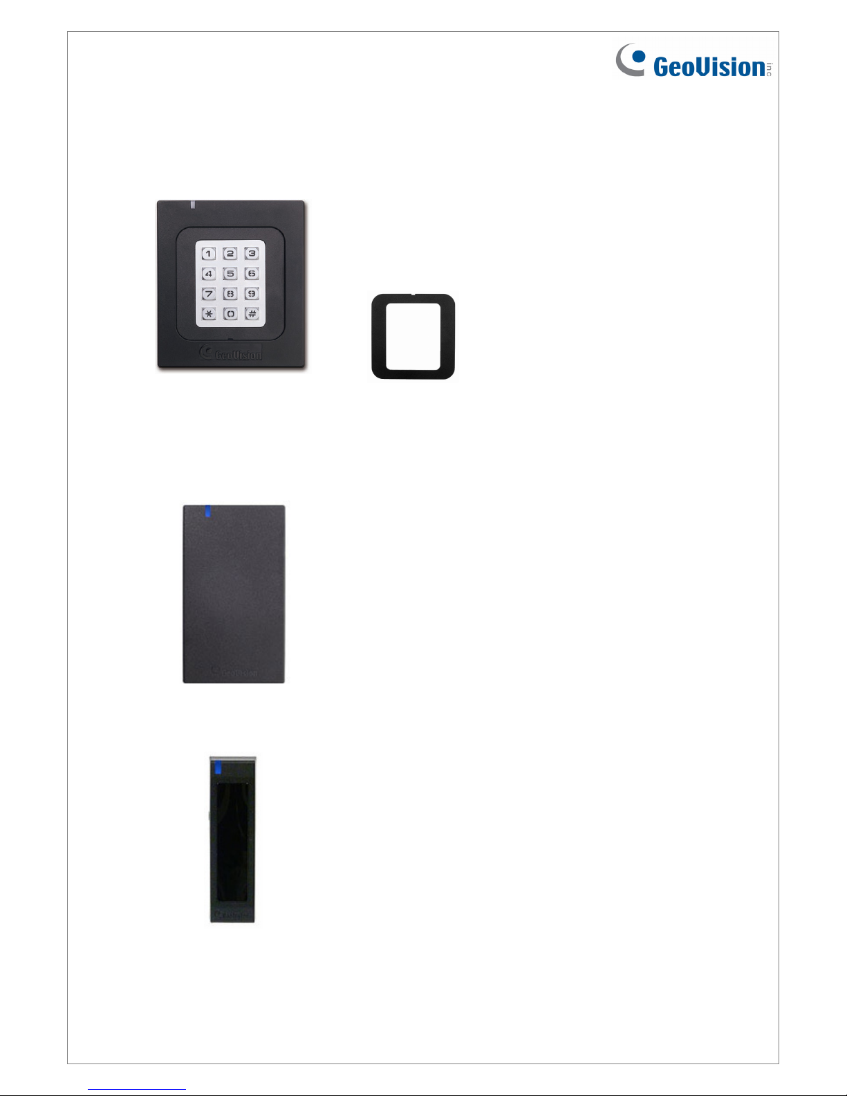
GV-RK1352 / R1352 / DFR1352 Card Reader
The content of this installation guide refers to the following readers:
•GV-RK1352 firmware V1.2
•GV-R1352 firmware V1.2
•GV-DFR1352 (Rev. B) firmware V1.2
Introduction
GV-RK1352 / R1352 / DFR1352 are card readers capable of recognizing identification cards.
GV-RK1352 comes with keypad, allowing it to also recognize PIN codes. GV-DFR1352 is
designed to be installed on the door frame.
Featured with the Wiegand and RS-485 outputs, the readers can be connected to any
standard access control panel. The readers are protected by a weather sealed and IP66
compliant housing for outdoor use.
July 14, 2015
2
Packing List
GV-RK1352
1. GV-RK1352 Card Reader
2. Screw x 2
3. Screw Anchor x 2
4. Front Cover Plate x 2
5. Software CD
6. Warranty Card
GV-R1352
1. GV-R1352 Card Reader
2. Screw x 3
3. Screw Anchor x 2
4. Security Torx
5. Software CD
6. Warranty Card
GV-DFR1352
1. GV-DFR1352 Card Reader
2. Screw x 2
3. Screw Anchor x 2
4. Front Cover Plate x 2
5. Software CD
6. Warranty Card
July 14, 2015
3
1. Physical Descriptions
1.1 Electric Wire
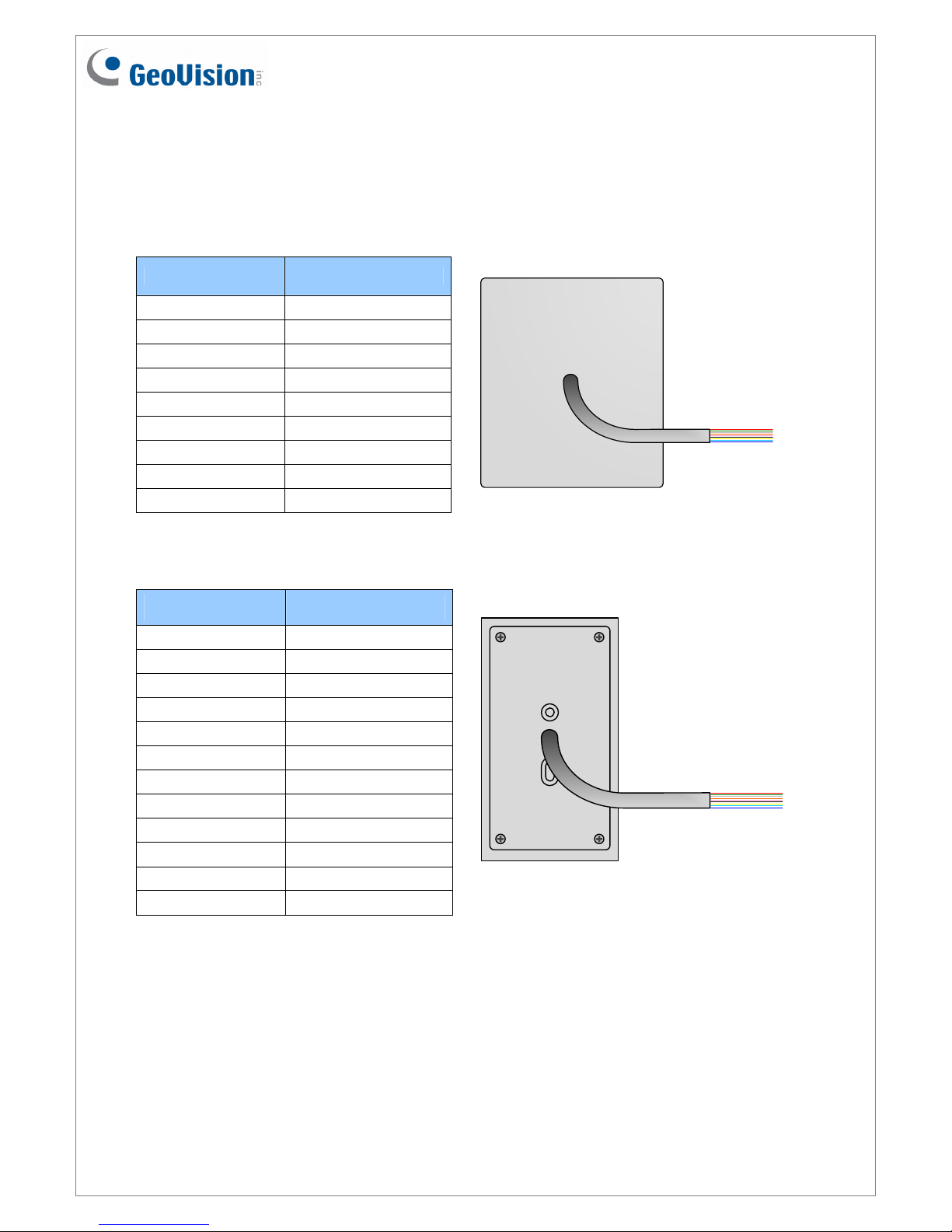
GV-RK1352
Wire Color Function
Red DC 7.5 ~ 12 V
Black GND
Yellow Beeper
Orange Green LED
Light Red Red LED
Green Wiegand Data 0
White Wiegand Data 1
Blue RS-485 +
Light Blue RS-485 -
Rear View
GV-R1352
Wire Color Function
Red DC 7.5 ~ 12V
Black GND
Yellow Beeper
Orange Green LED
Light Red Red LED
Green Wiegand Data 0
White Wiegand Data 1
Blue RS-485 +
Light Blue RS-485 -
Gray N/A
Purple N/A
Brown N/A Rear View
July 14, 2015
4
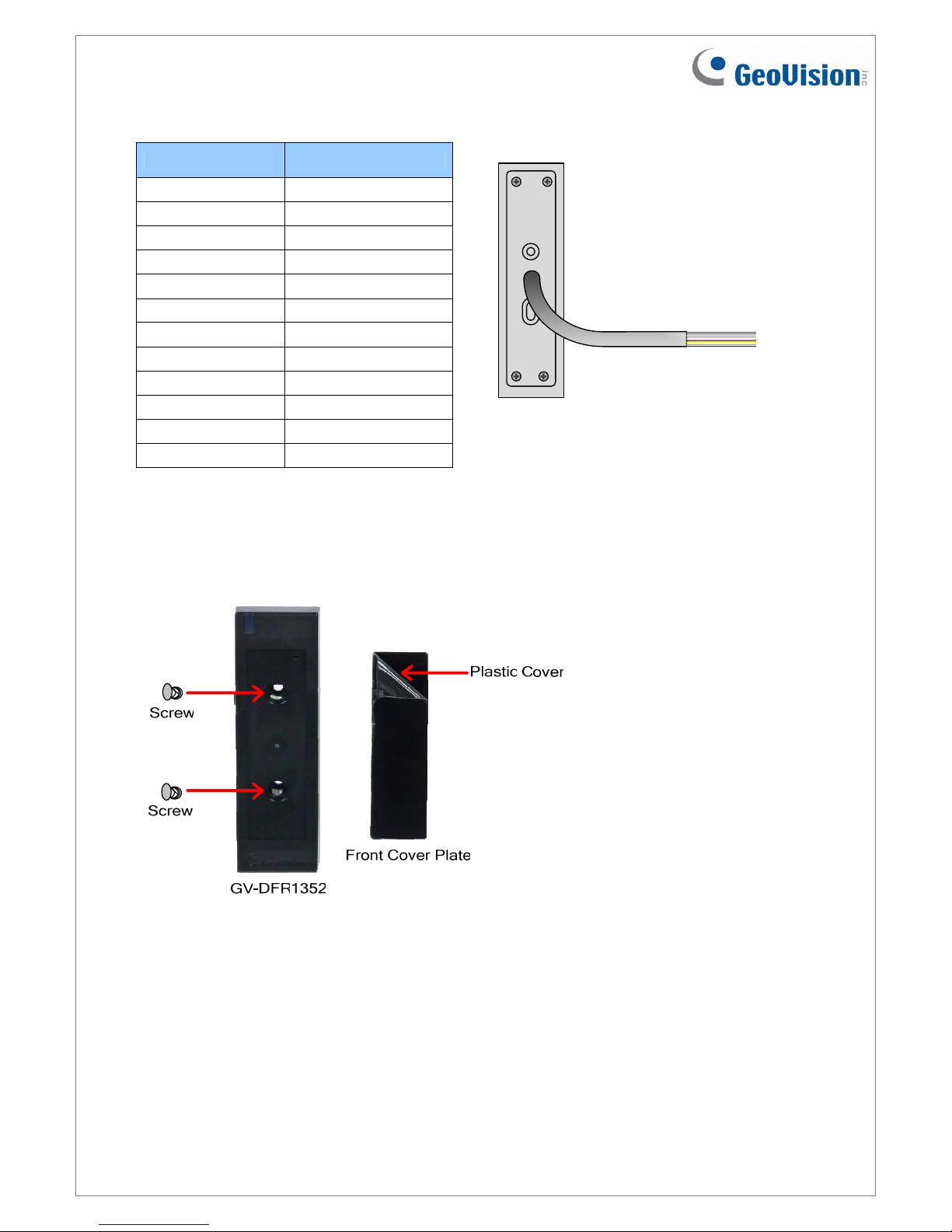
GV-DFR1352
Wire Color Function
Red DC 7.5 ~ 12V
Black GND
Yellow Beeper
Orange Green LED
Light Red Red LED
Green Wiegand Data 0
White Wiegand Data 1
Blue RS-485 +
Light Blue RS-485 -
Gray N/A
Purple N/A
Brown N/A Rear View
Install the GV-DFR1352 to the door frame using the supplied screws and screw anchors.
Before placing and sticking the front cover plate to the GV-DFR1352, remove the Plastic
Cover to prevent scratches to the cover after installed.

July 14, 2015
5
1.2 Keypad (GV-RK1352 Only)
When accessing an entry using GV-RK1352, you can enter the door’s PIN code on the
keypad or present the card and then enter the card’s PIN code on the keypad to be granted
access. The access mode is defined on GV-ASManager.
1. 0~9 Number Keys: Press the number keys to enter the PIN code.
2. # Key: Press the # key to confirm the PIN code.
3. ﹡Key: Press the ﹡key to cancel the PIN code.
1.3 LED Indicator and Beeper
In standby mode, the LED is blue. When a card is read, the LED flashes green and the
beeper beeps once.
The reader comes with external control wires for Green LED, Red LED and Beeper. You can
connect these control wires to a GV-AS Controller to change the default settings of the LED
and Beeper. For details on how to configure the settings, refer to 5. Changing the Settings of
Beeper and LED later in this installation guide.
Note: You can only connect the LED and beeper wires to GV-AS210 / 2110 / 410 / 4110 /
810 / 8110.
July 14, 2015
6
2. Connecting the Reader to GV-AS Controller
You can connect the readers to GV-AS Controllers through Wiegand or RS-485 interface.
Note that the connection between the reader and GV-AS Controller varies with different
controller models. To see how many readers can be connected to a GV-AS Controller, refer
to The Number of Readers Supported by GV-AS Controllers table at the end of this
installation guide.
Note:
1. GV-RK1352 / R1352 / DFR1352 is compatible with GV-AS100 / 1010 / 110 / 120 / 210
/ 2110 / 410 / 4110 / 810 / 8110. However, to enable the keypad function on GV-
RK1352, you can only connect GV-RK1352 to the controllers through the following
interfaces.
•GV-AS100 / 110 / 120: through Wiegand interface
•GV-AS1010: through RS-485 interface
•GV-AS210 / 2110 / 410 / 4110 / 810 / 8110: through Wiegand or RS-485 interface
2. Each GV-RK1352 / R1352 / DFR1352 consumes 60 mA of power. The total power
consumption of the output devices and readers connected to the GV-AS Controller
must be under 3A (for GV-AS210 / 2110), 3.5A (for GV-AS410 / 4110) or 5A (for GV-
AS810 / 8110). Connect an external power supply if the power supplied from GV-AS
Controller is insufficient.
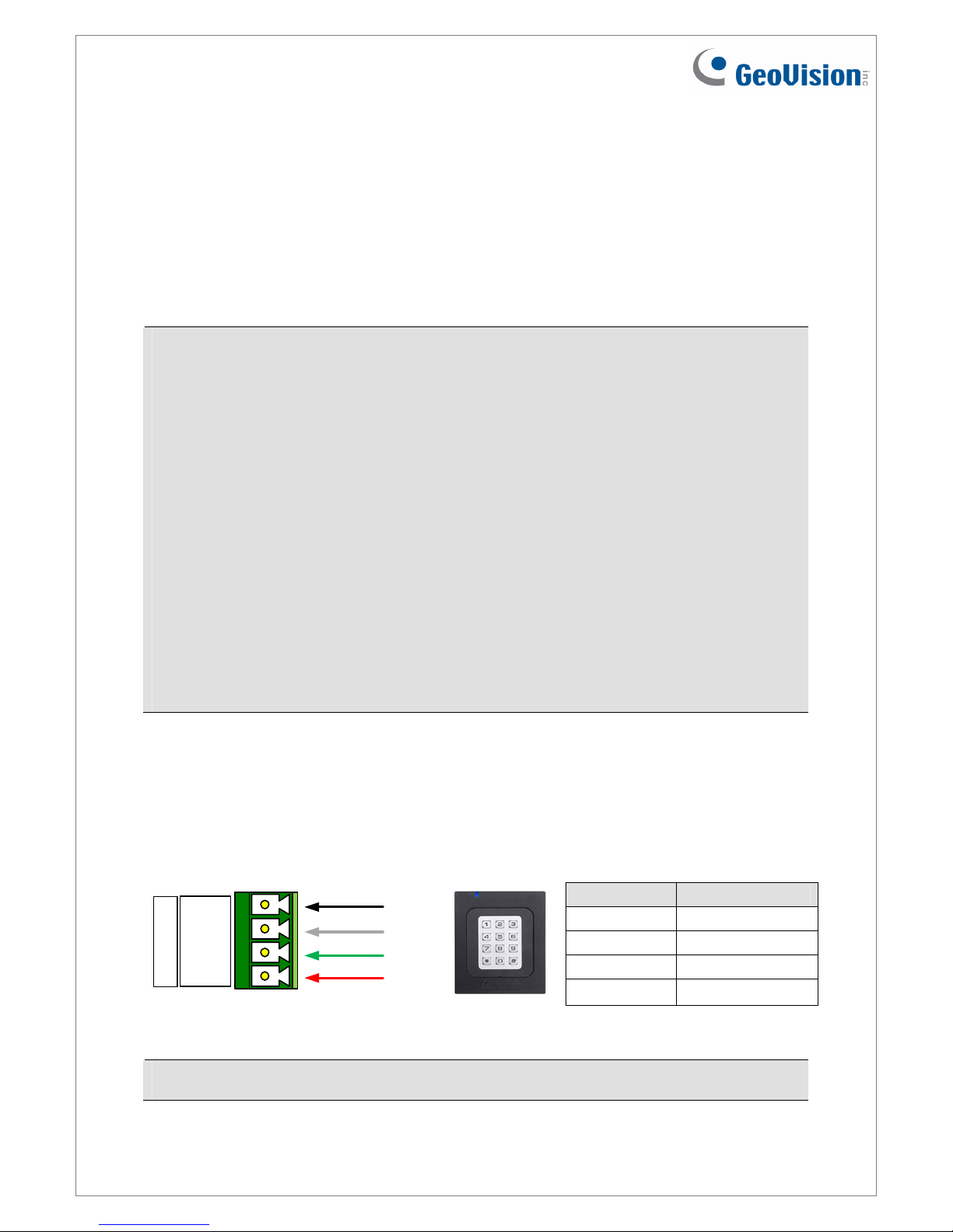
2.1 Connecting through Wiegand Interface
The following diagrams use GV-RK1352 and GV-AS810 Controller as an example. Up to
eight readers can be connected to GV-AS810 Controller through the controller’s Wiegand
interface.
Wire Color Function
Black GND
White Wiegand Data 1
Green Wiegand Data 0
Red DC 7.5 ~ 12V
(Black)
(Green)
(White)
(Red)
GND
D1
D0
12V
Wiegand A
GV-AS810 Controller GV-RK1352
or GV-R1352
Note: Connection through Wiegand interface is not supported for GV-AS1010.
July 14, 2015
7
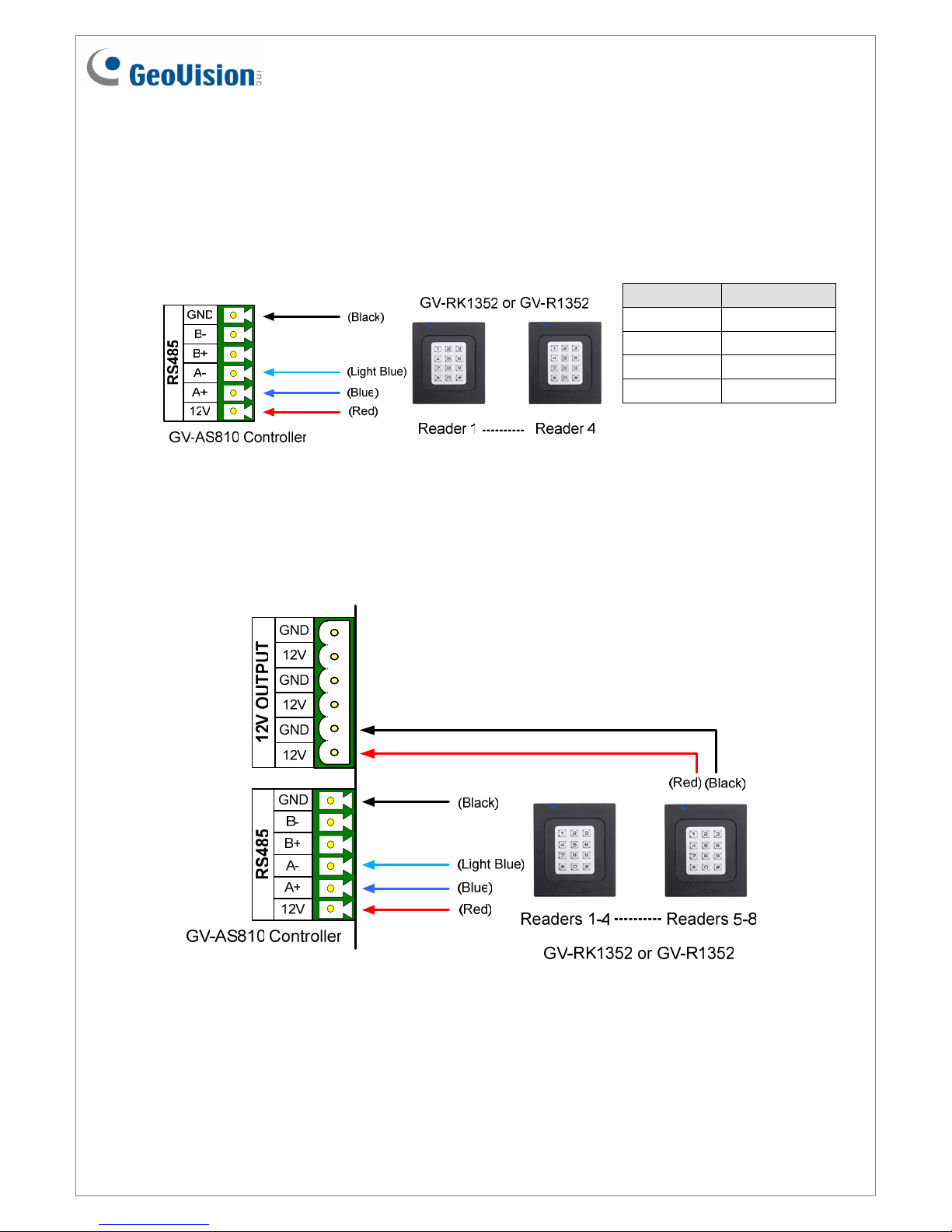
2.2 Connecting through RS-485 Interface
The following diagrams use GV-RK1352 and GV-AS810 Controller as an example. Up to
eight readers can be connected together to the RS-485 interface on GV-AS810 Controller.
zConnecting four or less readers to GV-AS810 Controller:
Wire Color Function
Black GND
Light Blue RS-485 -
Blue RS-485 +
Red DC 7.5 ~ 12V
zConnecting five or more readers to GV-AS810 Controller:
For readers five to eight, connect the RS-485 cable to the RS-485 interface on GV-
AS810 Controller and then connect the 12V power output and GND of the reader to a
12V DC power output on the controller.
July 14, 2015
8
2.2.1 Defining Readers on GV-AS Controller Web Interface
Since multiple readers can connect to GV-AS Controller using one RS-485 interface, you
need to specify which door each reader controls. This section explains how to define readers
on the Web interface of GV-AS Controller. On the Web interface, you can also set the reader
to read the GID or UID on GV-AS ID Cards / Key Fobs. Note that the Web interface of
different GV-AS Controller models varies.
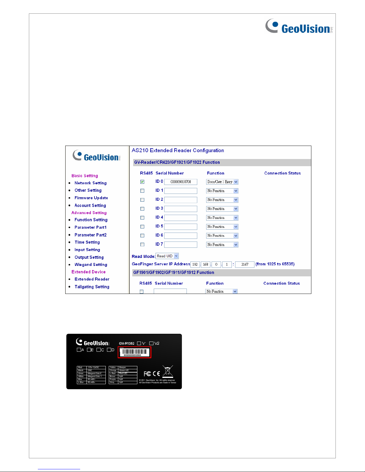
1. On the controller’s Web interface, click Extended Reader. This dialog box appears.
2. In the GV-Reader/CR420/GF1921/GF1922 section, select the RS485 checkbox in front of
the ID number and type the Serial Number on the rear panel of the reader. The ID
number will be assigned to the reader.
3. Select a door/gate for the reader from the Function drop-down list.
July 14, 2015
9
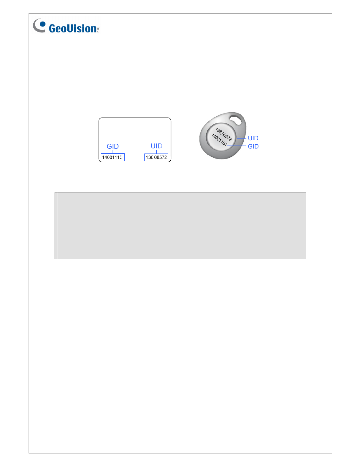
4. Next to Read Mode, select Read UID or Read GID to set the connected readers to read
UID (unique identifier) or GID (GeoVision ID) on GV-AS ID Cards / Key Fobs.
If you select Read GID, make sure there are two numbers on your GV-AS ID Cards / Key
Fobs as shown below. If there is only one number on your GV-AS ID Cards / Key Fobs,
GID is not supported, and you must select Unique Identification (UID).
5. Click Submit.
Note:
1. When you click Submit on the Extended Reader page of a GV-AS1010 / 210 / 2110 /
410 / 4110 / 810 / 8110, all readers connected through RS-485 interface will reboot.
2. GID ID format is only supported in GV-RK1352 / GV-R1352 / GV-DFR1352 (Rev. B)
V1.2 or later.
3. If you are using third-party cards or key fobs, you must set the reader to read UID.

July 14, 2015
10
3. Installing the GV-R/RK/DFR Config AP
The GV-R/RK/DFR Config AP allows you to set the reader’s beeper / LED, ID number,
master / slave status, and whether it reads UID or GID. When using the Config AP, the
reader needs to be connected to a PC through GV-COM, GV-Hub or GV-NET/IO Card V3.1.
You can install the Config AP from the Software DVD or GeoVision Website. To use a GV-
COM, GV-Hub or GV-NET/IO Card V3.1, you also need to install GeoVision USB Device
Driver.
Installing from Software CD
1. Insert the software CD and the Install Program window will pop up automatically.
2. Select Install GeoVision USB Device Driver.
3. In the GeoVision USB Driver Installer window that appears, select Install.
4. Go back to the Install Program window, and select Run GV-Reader Config Utility.
Downloading from GeoVision Website
1. Go to the Software Download and Upgrading page of GeoVision Website:
http://www.geovision.com.tw/english/5_8_AS.asp
2. Select GV-Reader from the drop-down list, and click the Download icon of
GV-RK1352 & GV-R1352 & GV-DFR1352 Config Utility.
3. Select Driver from the drop-down list and click the Download icon of GV-
USB Device Driver.
Other manuals for GV- RK1352
3
This manual suits for next models
4
Table of contents
Other GeoVision Card Reader manuals

GeoVision
GeoVision GV-R1352 V2B User manual

GeoVision
GeoVision GV- DFR1352 User manual

GeoVision
GeoVision GV-R1352 User manual

GeoVision
GeoVision GV-PCR310 User manual

GeoVision
GeoVision GV- RK1352 User manual

GeoVision
GeoVision GV-Reader 1251 User manual

GeoVision
GeoVision GV-CR420 User manual

GeoVision
GeoVision GV- RK1352 User manual

GeoVision
GeoVision GV- RK1352 User manual

GeoVision
GeoVision GV-R1352 V2B User manual


