Foton Accessories FLAMINGO DUO User manual
Video Jib
User Manual

Table of contents
Introduction ............................................................... 3
Preparing the Jib for work ............................................ 4
Transportation .......................................................... 12
Conservation and maintenance .................................... 12
arranty ................................................................. 13
Technical specification ................................................ 14
Contents .................................................................. 15
Foton Accessories
www.fotonexport.com
Made in Poland
2

Introduction
We'd like to thank you for choosing our Flamingo Jib. We've
put a lot of heart and work into its creation, doing our best,
to give you functional and innovative product. Our top
employees dedicated themselves to the production process,
making sure that working with Flamingo will be flawless and
enjoyable. hanks to many new and unique functions our Jib
will improve your workflow and open up new creative
possibilities.
We hope that you'll enjoy our product!
Foton Accessories eam
3
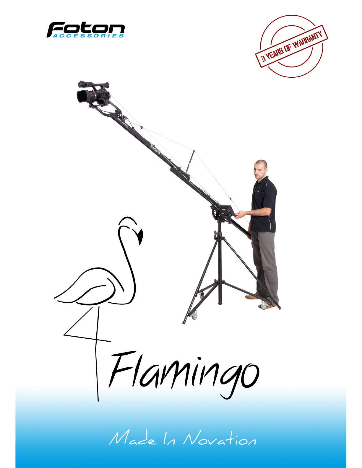
Preparing the Jib for work
For your own safety and comfort we
recommend Foton Accessories STF Tripod
(pic. 1).
Flamingo may be also mounted on any
massive tripod meeting following
requirements:
•load of 40 kg minimum,
•distance between legs and central
axis is at least 75 cm,
•the tripod is supplied with spreader
securing legs from accidental colapse
caused by weight,
•the tripod is supplied with mounting
3/8" screw at least 7 mm long (you
should never use 1/4" to 3/8"
reduction!),
•maximum tripod height should be no
more that 150 cm.
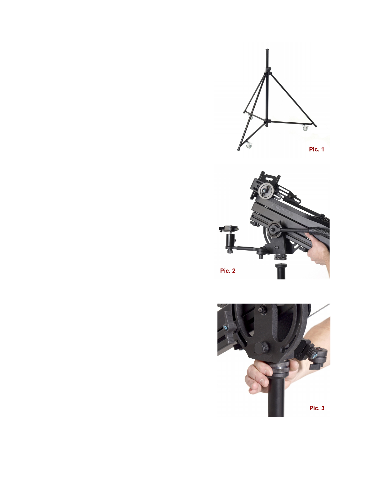
The tripod should be unfolded and secured
against accidental folding. If it's supplied
with extension column, then it should be
extended as necessary and locked. The Jib
should be put on tripod (pic. 2) and screwed
tightly with a knob placed at the bottom
(pic. 3).
4
Attention! The knob should be lock tightly, so there is virtually no
clearance between Tripod and Jib.
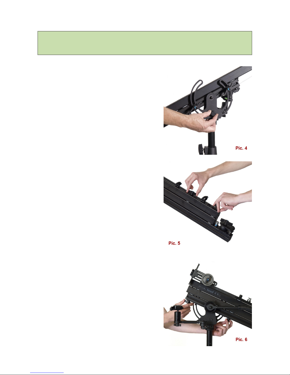
After mounting the Jib on the tripod you
should loosen four knobs located in its
upper part as well as two located at the
bottom. Then you should extend the Jib to
its full length.
The extended jib should be secured by
locking all those knobs again (pic. 5 & 6).
To calculate correct counterbalance weight,
you have to multiply the filming device
weight (total - with all attached
accessories) by 2.5x factor.
Example: he filming device weights 3 kg
which we multiply by 2.5. Result is 7.5 kg
and that is the optimal counterbalance
weight (including neck with caps which is
2 kg). In that case we should use weights
of 5 kg total. Our total counterbalance
weight with neck, caps and weights will be
7 kg in this case.
5
Before placing the weights, you must
unlock the cap from the upper part of the
neck holder, open it, put the neck with
weights on and close the holder back. Then
you have to secure the neck holder by
locking the cap tightly (pic. 7).
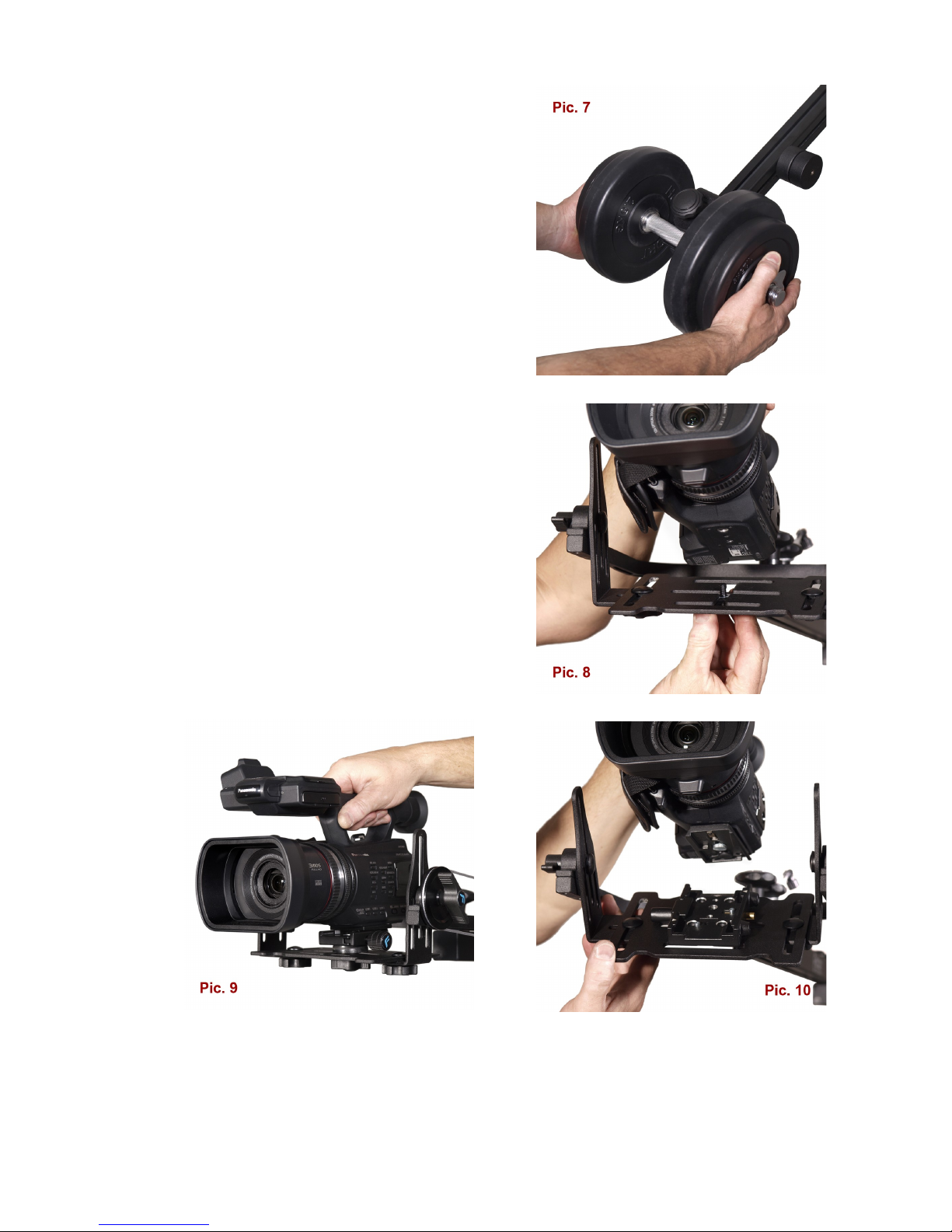
Filming device may by mounted on the Jib
with 1/4" or 3/8" screw (pic. 8). You may
also use included rapid release socked PRO
type (pic. 9).
Optionally, the crane may be supplied with
Manfrotto 577 socked and 501PL plate
(pic. 10).
6
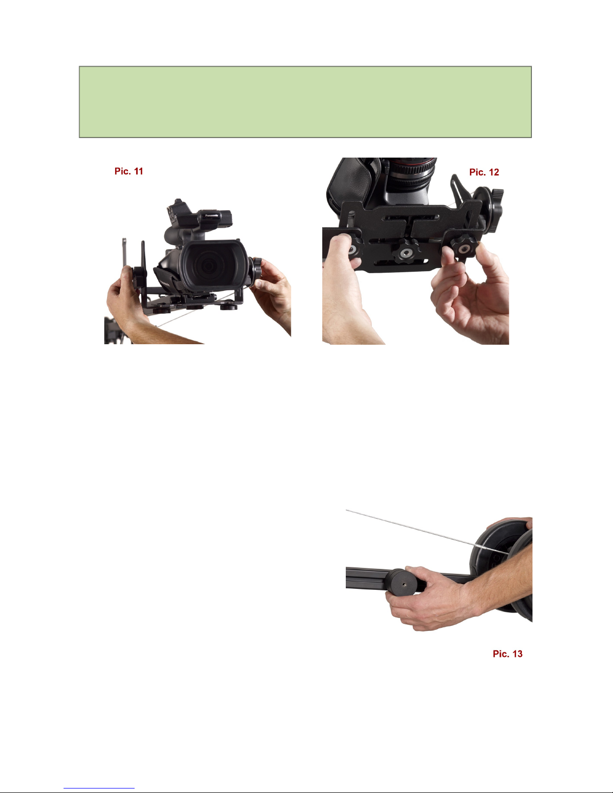
Attention! For a proper Crane operation it is very important to find
center of gravity of the filming device. This process must be
conducted experimentally.
Special knobs for this operation are located at the bottom and on the sides of
the mounting plate. By moving the filming device in grooves of the plate, you
have to find the point in which your camera or camcorder keeps its position at
any angle and then secure knobs tightly (pic. 11 & 12).
This process must be conducted only once for a specific filming device.
After mounting the filming device you
should slowly and carefully unlock vertical
movement knobs and check if Crane is
balanced properly.
There are special weights for fine
adjustment, placed on sides of rear part of
the Jib (pic. 13).
If counterbalance weight is incorrect, you'll
need to add or subtract weights from
counterbalance neck, until the Jib keeps its
balance.
7
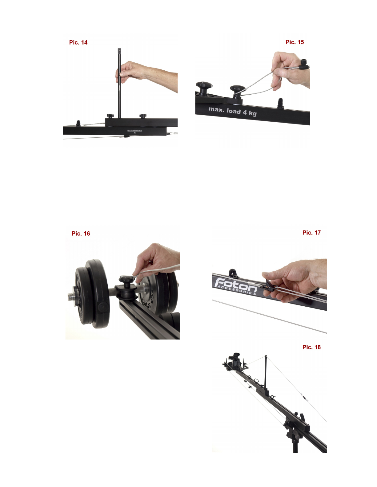
Next you’ll need to install the pendant cord. In order to do it, you'll have to
mount the strut on the Jib (pic. 14). The Cord has two loops - one on each
end. The first loop should be put on the cap holding the camcorder mounting
plate, placed in the front (pic. 15) and the second loop - on the counterweight
handle cap in the rear (pic. 16).
To get the proper tension you’ll have to use
the „click-type” tightener placed on the cord
(pic. 17).
Next you’ll have to install the drive cord
onto the pulleys located in the front and in
the middle of the Jib (pic. 18). This process
is conducted in a similar manner as
8
installing the pendant cord. Before installing
the drive cord, you should set the most
convenient handle position, so that you
won't be restricted in further maneuvers.
The tightener must be kept at a distance
from the pulleys.
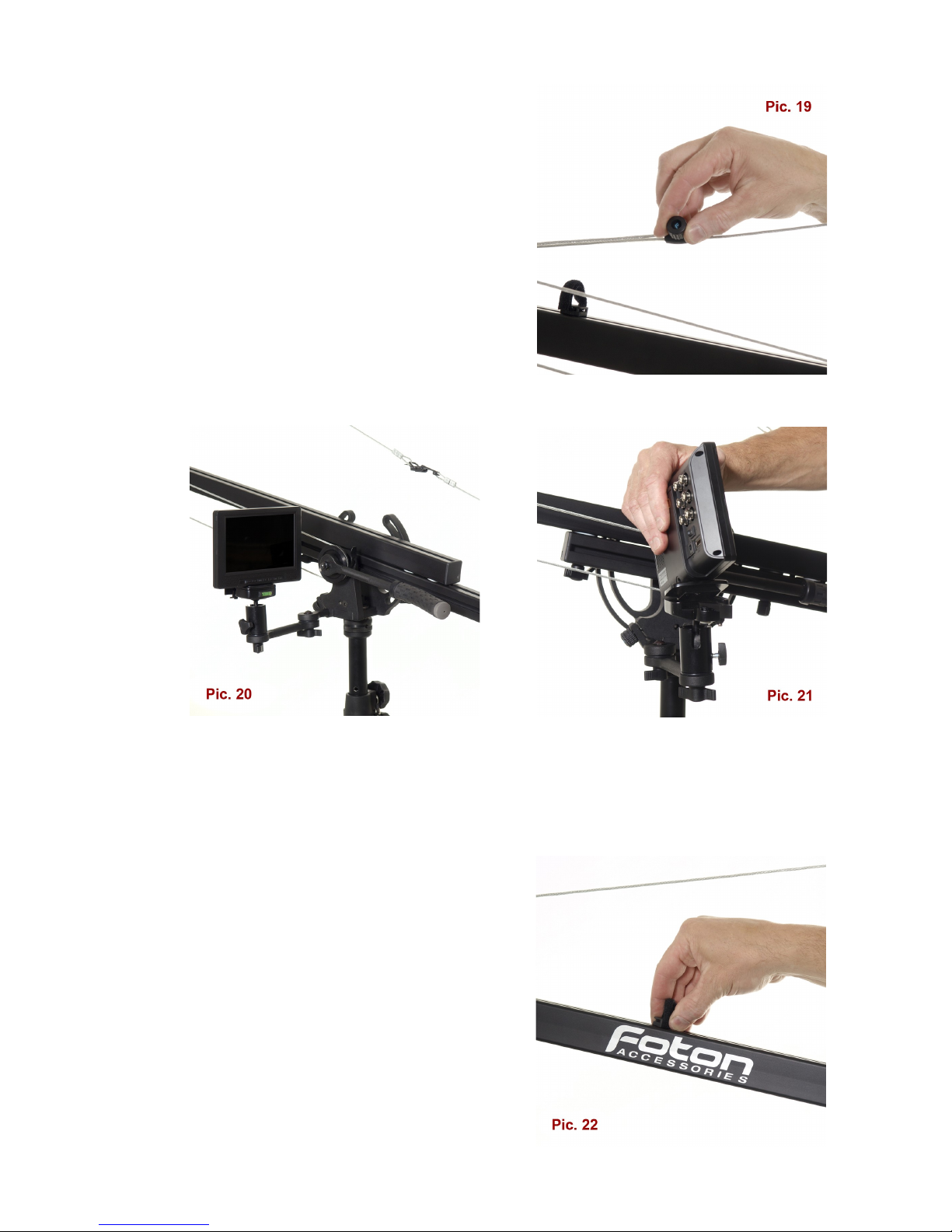
orking length of Jib may be reduced for
your personal needs. In that case you'll
need to adjust length of the cords as well
(pic. 19).
e supply the Flamingo with convenient holder for LCD screen which keeps its
position independently of the Jib's movement. The holder is adjustable in all
planes and its sturdy design guarantees stability. There is a quick release
socket included for easy and secure LCD screen mounting (pic. 20 & 21).
For easy wires management we included
several velcro loops. Loops are movable so
you may set them in an optimal position. To
do so, you'll need to turn the loop basis by
90 degrees, move to a destined place and
lock by turning 90 degrees back (pic. 22).
9
Remote controller may be mounted on the Jib's drive handle as it has a
standard 15 mm diameter.
The horizontal movement lock is located on the Jib's side. This lock should be
used only to secure Jib in a specific position. You need to unlock this knob
before moving the Jib. Failure in doing so my result in accidental Jibs
detachment from tripod (pic. 4 – page 5).
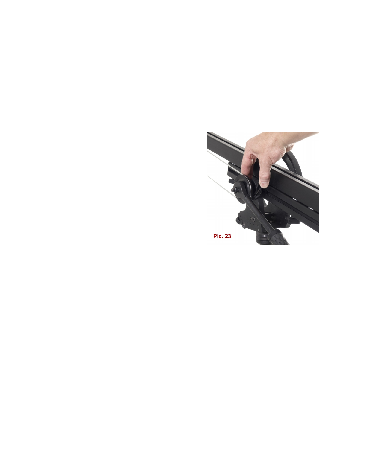
Pendant cord lock (pic. 23) located next to
the drive handle lets you work in two
modes:
- manual – lock is released and the filming
device is operated with handle,
- automatic – you set the filming device in
the desired position and then turn the lock
on; the filming device will keep its position
independently of the Jib's movement
(pic. 23).
Lock regulation allows you to use the device in the semi-automatic mode with
a possibility of fine adjustment.
Flamingo may be easily adapted to work with Foton Sliders – SL9 and SL130
(94 and 130 cm long).
You can also mount the slider on tripods or set on the floor or another flat
surface. Owing to our ADAPSL adapter it may be also mounted on the Jib
(pic. 24 – page 11).
10
Other manuals for FLAMINGO DUO
1
Table of contents
Other Foton Accessories Camera Accessories manuals


Popular Camera Accessories manuals by other brands

Viltrox
Viltrox EF-NEX Mount instructions

Calumet
Calumet 7100 Series CK7114 operating instructions

Ropox
Ropox 4Single Series User manual and installation instructions

Cambo
Cambo Wide DS Digital Series Main operating instructions

Samsung
Samsung SHG-120 Specification sheet

Ryobi
Ryobi BPL-1820 Owner's operating manual


