Fluid E920 User manual

Owners Manual
Wheelchair Acces-
sible

2
Contents
1. Contents of E920 Box.
2. E920 Assembly Instructions.
3. E920 Control Arm.
4. E920 Slider Arm Kit.
5. Tank Filling and Water Treat-
ment.
6. Long Term Water Treatment
and Basic Operation.
7. The E920 Ergometer.
8. Maintenance/Troubleshooting.
9. Tank Belt Drive Adjustment.
10. Parts List and Warranty.
Do not remove hands while crank is in
motion. The crank will continue to rotate
and could cause injury.
As with any piece of fitness equipment,
consult a physician before beginning your
E920 exercise program.
CAUTION
WARNING

3
Box Contents E920
Hex Key
M3x130x25
4x Spring Washers
M8
2x Mainframe Bolts
M10x 25
4x Frame Bolt
Washers
21x11x2
1x Seat and Base
1x Main Frame with Telescoping Tube and
Internal Gas Assist Shock
1x Fill Funnel and
Hose
3x Frame levelers
1x Multi-Tool
2x Mainframe Nylock Nut
M10x2
1x M6
Hex Key
E-920 Slider
arm kit
Slider Arm Kit includes 1x Slider Arm
Assembly Right (includes right han-
dle), 1x Slider Arm Assembly Left
(includes left handle), 2x Yellow Ad-
justment Knobs with Nylon Spacers.
Owners Manual
2x AA Batteries
8x Chlorine Tablets
1x Blue Dye
Touch Up Paint
4x Telescoping
Tube Attachment
Bolts M8x15
4
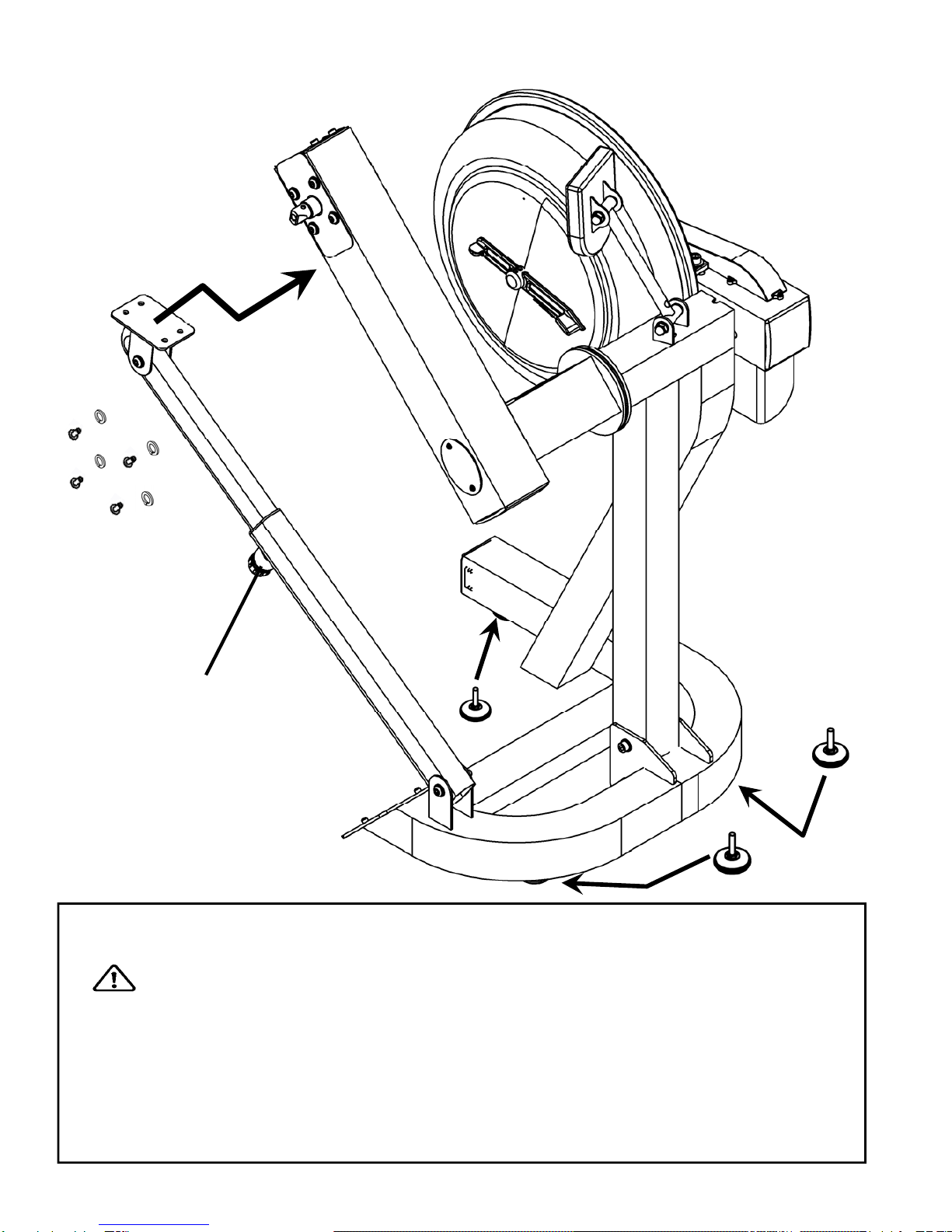
E920 Assembly Instructions
Adjuster Knob
Step 1: Remove contents from box. Attach telescoping tube to the underside of the
control arm using 4x M8x15mm bolts and 4x M8 spring washers.
The control arm is heavy and will swing freely during this stage of assembly. The ad-
juster knob is pre-tightened from the factory in the optimal position for assembly in rela-
tion to the control arm. Do not loosen the Adjuster knob until the telescoping tube has
been safely secured to the underside of the control arm.
Step 1a: Thread the 3x foot levelers into underside of base. Adjust as required.
CAUTION
4x 8x15mm Bolts
and 4x M8 Spring
Washers
3x Foot Leveler

5
E920 Assembly instructions
M10 Nylock Nut
21x11x2 Washer
M10x25mm Bolt
Step 2: Attach base plate to lower mainframe using 2x
M10x25mm bolts, 2x M10 Nylock nuts and 4x 21x11x2 washers.
Step 3: Tilt the seat rearward until transport wheel is engaged. Secure the seat in
any of the 4 adjustment slots, or leave off entirely if wheelchair access is required.

6
The E920 Control Arm
Crank arm bolts: Loosen
all 8 bolts slightly before
adjusting/tightening chain.
Handgrip: Loosen knob
to adjust handle position
from 0-90 degrees.
E920 Slider Arms: Refer to
following assembly page.
Inspection plate: Open to check chain tension.
With a screwdriver or other implement, check
tension just behind front sprocket.
Note: Aproperly adjusted chain will have 3mm-
5mm of slack only. See top of page for adjust-
ment details.
Warning: Do not check chain tension by
Hand!
Chain tensioning bolts: Allows for tightening the chain or adjustment from side to side.
Make sure when tightening only to adjust the same amount for both bolts, otherwise the
sprocket will be misaligned.
Note: Tightening the right bolt only (turning clockwise) will pull the right side of the crank
assembly toward you, tightening the left will pull the left side toward you. Use this feature
to realign the rear with the front sprocket if needed or when changing to a new chain.
Adjustment Knob: Loosen to allow
the control arm to travel through 90
degrees of travel. Note the tele-
scoping tube is gas assisted.
Tighten securely when desired
workout position is reached.

7
E920 Slider Arm Kit Installation Instructions
Slider Arm Kit includes 1x Slider
Arm Assembly Right (includes right
handle), 1x Slider Arm Assembly
Left (includes left handle), 2x Yellow
Adjustment Knobs with Nylon Spac-
ers and 1x 3mm Allen key.
Note: Slider Arms are marked ‘L’
and ‘R’.
Improper installation will result in
uneven Slider Arm adjustment.

8
E920 Slider Arm Kit Installation Instructions
Step 4: Repeat steps 1-3 to install right
Slider Arm onto axle.
Step 1: Mount the left Slider Arm onto
the axle using the yellow indicator hole
to align the slider and axle.
Step 2: Tighten the set screw onto the axle
and into the yellow indicator hole using the
3mm Allen key.
Step 3: Thread Adjustment Knob onto
axle to secure the assembly.

9
Using the E920 Slider Arm
The E920 Slider Arm Kit offers the user an entire range of added
resistance settings and the ability to perform additional upper
body workouts.
To adjust, simply loosen the Adjustment Knobs, move SliderArm
to desired length and secure. Very little tension is needed.
What do the numbers mean?
The numbers represent the length (in cm) from the center of the
axle to the center of the handgrip shaft bolt. The shortest Slider
Arm length is 12cm and the maximum length is 21cm. The range
of adjustment is 9cm.
Additional Exercises: Training can now be achieved with both
left and right Handgrips moving parallel , rather than in an
opposed motion.
Step 1: On the right Slider Arm Assembly, remove the adjust-
ment knob, loosen set screw and remove Assembly from axle.
Step 2: As shown below, rotate right Slider Arm 180 degrees
and reinstall onto axle. There is an additional screw locator hole
located on opposite side of axle .

10
Tank Filling and Water Treatment
Tank
plug
Filling hose and
funnel
Note: A large bucket is required for filling (Not included).
In areas where tap water quality is known to be poor, FDF recommends the use of
distilled water.
Water Treatment Procedures:
1. Add Chlorine tablet.
2. Wait a minimum of 72
hours. Then add very small
amount of blue dye and check
for desired color. Important!
Do not add blue dye for at
least 72 hours following Chlo-
rine treatment. The blue dye
adds visual appeal as well as
cutting down the amount of light
affecting the tank water, thus
extending the amount of time
between water treatments.
Note: The blue
dye is extremely
concentrated and
will readily stain
carpet or clothing.
Caution: Use a drop cloth when filling or
adding blue dye
Blue Dye
Open the tank plug and insert
hose into tank (rotating the im-
peller slightly may be neces-
sary to allow the hose to
pass), move the tank adjuster
handle to level 20 and begin
filling. Do not fill the tank
higher than the level indicator
on the front of the clear shell.
A properly filled tank holds ap-
proximately 8 liters of water.
Do not under any circum-
stances put fingers into the
tank. Use the end of the hose
to move the impeller should
the need arise.
WARNING
Table of contents
Other Fluid Fitness Equipment manuals