Fisher LNS-T31A User manual

Following checks and confirmations should be taken for safety.
Check the following things by the time of the cabinet assembly after the lens
replacement.
1. Check the lens is securely fixed.
2. Check the proper wiring and the wires are fixed properly.
3. Check each connector is connected properly.
4. Check no wiring is tangled on the gear of lens motor or the other mechanical parts.
5. Check no parts is missing, or no mounting part is loose.
LCD PROJECTOR LENS
MODEL LNS-T31A/W31A/T32
LENS REPLACEMENT PROCEDURE
NOTES ON LENS REPLACEMENT
Lens replacement should be performed by the qualified service personnel.
It should be followed by this procedure precisely.
Before attempt to replace the lens, confirm the model number (both the LCD
projector and the lens) and use the proper lens.
The lens cover is on the lens for protection. Be sure to remove the lens cover
before installation.
When installing or removing the lens, be careful not to stain, scratch or
damage the lens.
If you have any questions, contact the dealers.
Following parts are contained in the packing.
1AA6P1P3188A- (ICYDA-A)
PARTS LIST
● LENS
● LIGHT-BLOCK SHEET BASE
● DRIVER (3 mm, Green)
● DRIVER (4 mm, Yellow)
● LIGHT-BLOCK SHEET For LNS-T31A
For LNS-W31A
For LNS-T32
1 piece
1 piece (Part No. 610 310 8001)
1 piece (Part No. 610 287 7328)
1 piece (Part No. 610 275 6029)
1 piece Type PB1 (Part No. 610 310 7950)
1 piece Type PC1 (Part No. 610 310 7967)
1 piece Type PF1 (Part No. 610 310 7974)
NOTE; Lens installation is different in cabinet design and lens attachment method
(Type A, B and C). Before installation the lens, check cabinet design and
proper installation should be made.
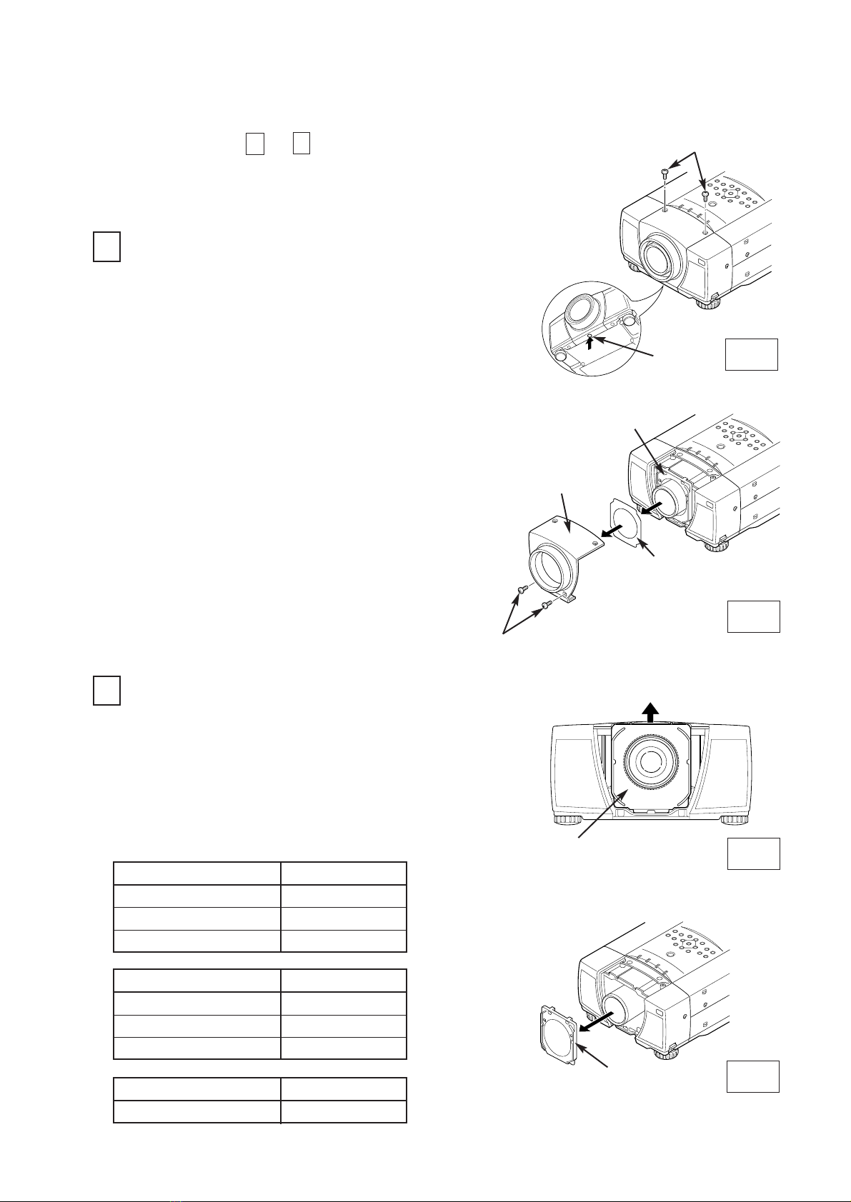
Fig-1
Fig-2
Fig-3
Fig-4
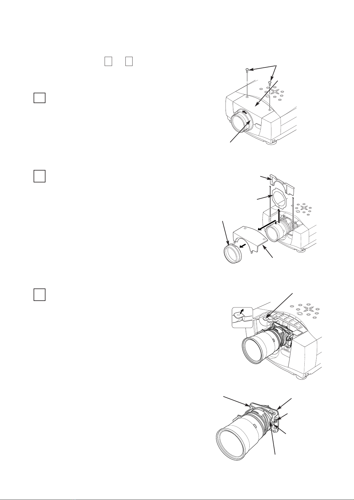
SCREW "A"
Remove 2 screws-A.
Press the button (or remove 2 screws-B) on
the lower of the lens cover and remove the
lens cover.
Remove the light-block sheet from the light-
block sheet base.
LENS REPLACEMENT PROCEDURE (FOR "A" TYPE )
REMOVE THE LENS COVER AND LIGHT-
BLOCK SHEET (See Figure-1 and 2)
1
1.
2.
2REMOVE THE LIGHT-BLOCK SHEET BASE
(See Figure-3 and 4)
Perform the steps to for lens replacement.
16
BUTTON
LENS COVER
LIGHT-BLOCK
SHEET BASE
SCREW "B" (Some models)
LIGHT-BLOCK SHEET
LIGHT-BLOCK
SHEET BASE
First set the lens at the center position with lens
shift adjustment.
3.
Slide the light-block sheet base upward.
Remove the light-block sheet base.
1.
2.
LIGHT-BLOCK
SHEET BASE
LENS MOTOR PARTS NO.
(LOCATED ON THE LENS)
LENS
MOTORASSEMBLY
ZOOMMOTOR
FOCUSMOTOR
LENS
MOTORASSEMBLY
ZOOMMOTOR
FOCUSMOTOR
LNS-T31A
6450477713
6450477157
6450477140
LNS-W31A
6450477706
6450477133
6450477126
-2-
LENS
MOTORASSEMBLY LNS-T32
6450630323
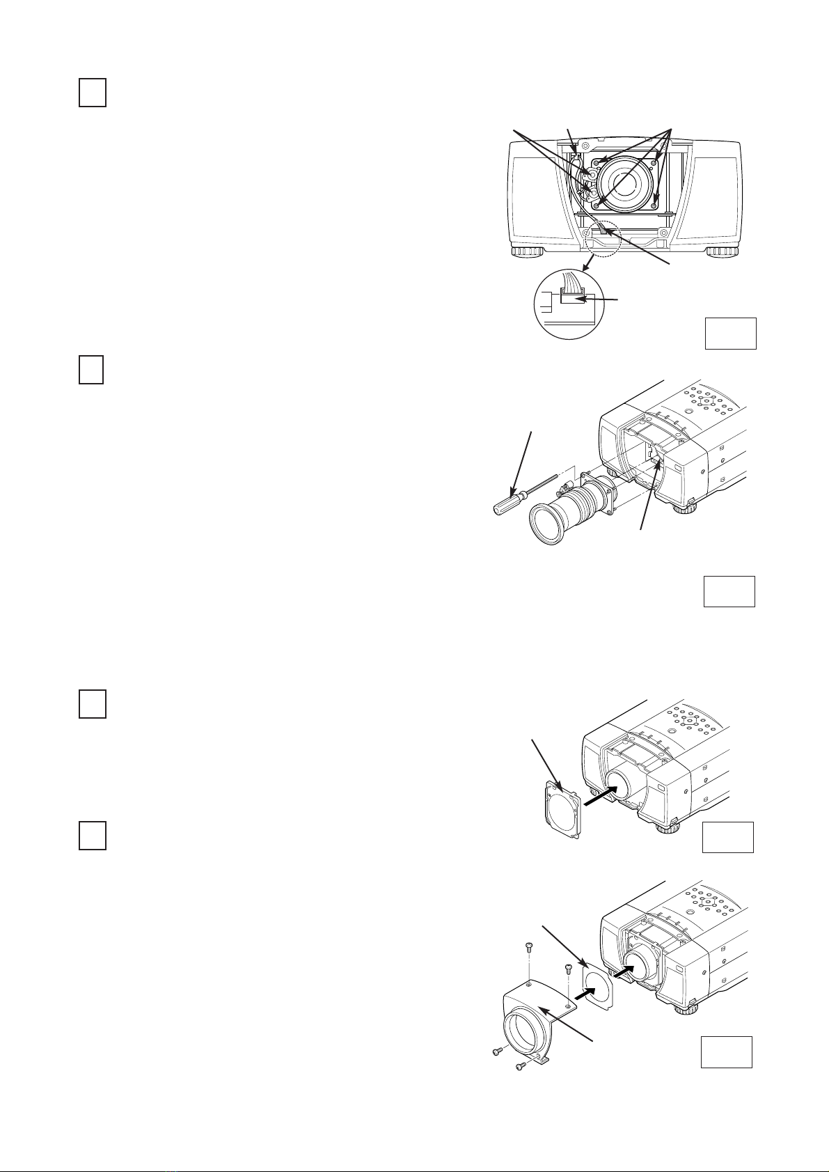
Fig-6
Fig-7
Fig-8
3REMOVE THE LENS (See Figure-5 and 6)
Remove the connector "K16J" of the circuit board.
Remove the lens motor lead from lead holder.
Remove screws-C (4 screws) which fastens the
lens and remove the lens. Use the driver (3 mm,
Green) included with the lens to remove the
screws.
1.
2.
DRIVER
IN THE LENS
LENS MOUNTING
BRACKET
4MOUNT THE LENS (See Figure-5 and 6)
5MOUNT THE LIGHT-BLOCK SHEET BASE
(See Figure-7)
6MOUNT THE LIGHT-BLOCK SHEET AND
LENS COVER (See Figure-8)
Be careful not to drop the lens when removing the
screws.
After using, save the driver for latter use.
Remove protective caps (front and back) on the
lens.
Mount the lens on lens mounting bracket with 4
screws. (locate motor on left side).
Use the driver (4 mm, Yellow) included with the
lens to fasten the screws.
1.
2.
After using, save the driver for latter use.
Connect the lens motor lead to the connector
"K16J" of the circuit board.
Connect the lens motor lead to the lead holder.
3.
4.
Mount the light-block sheet base to the projector.
Mount the light-block sheet to the light-block sheet
base as shown in the Figure-8. (In the same
position as the removed sheet has been placed).
Use the sheet included with the lens.
Make sure the part no. and mark (TOP and BACK)
on Light-Block Sheet and set them properly.
Mount the lens cover with the screws.
1.
2.
3.
1.
LENS COVER
LIGHT-BLOCK
SHEET
LIGHT-BLOCK
SHEET BASE
(Part No. 412 062 3705)
LENS
MOTOR
LEAD
HOLDER
CONNECTOR "K16J"
LENS MOTOR LEAD
SCREW "C"
Fig-5
-3-
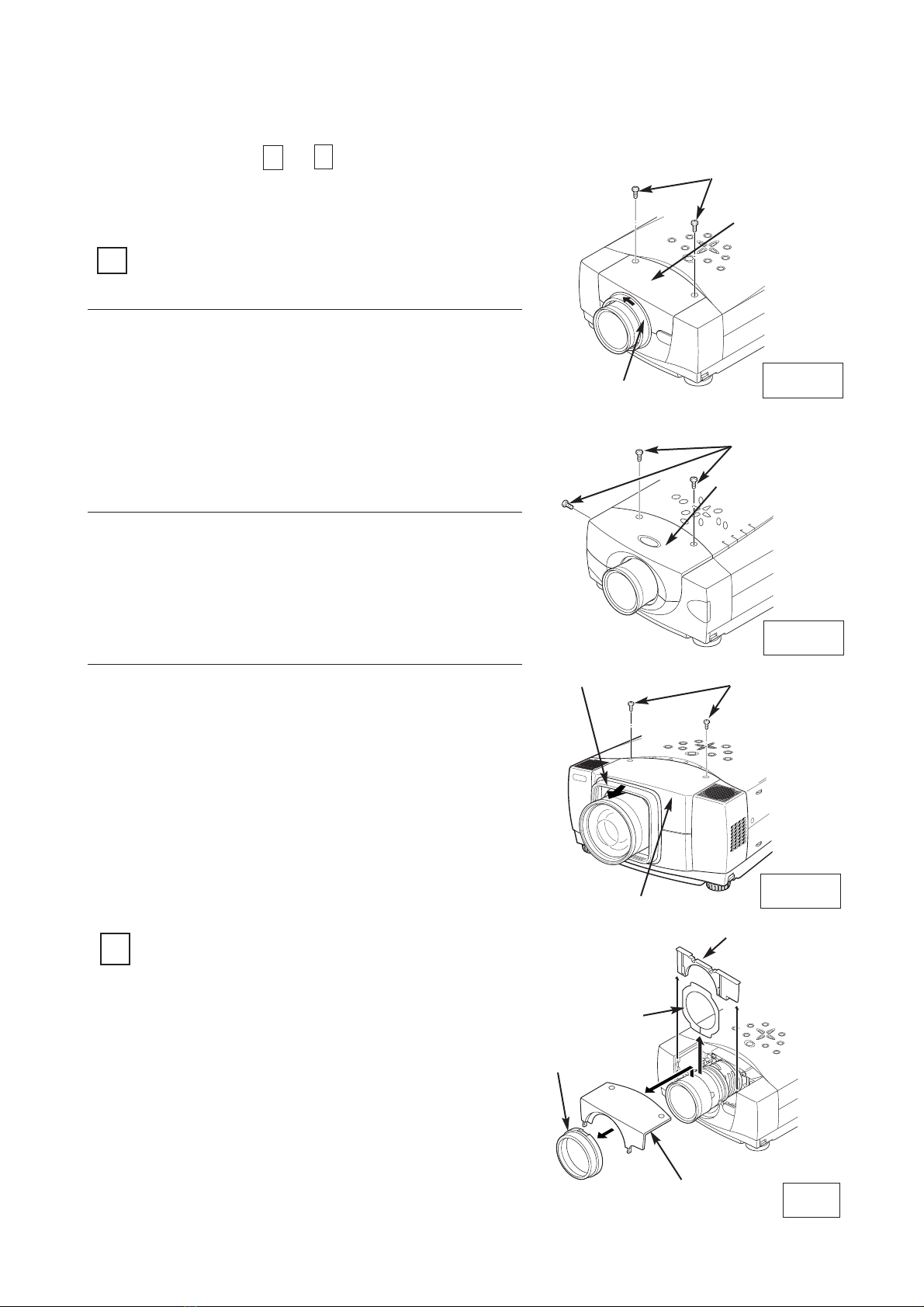
Turn the lens cover to counter-clockwise and
pull it toward front and remove the Lens
Cover.
Remove 2 Screws-A.
Remove the front cabinet
REMOVE THE LENS COVER AND
FRONT CABINET
1
1.
2.
2REMOVE THE LIGHT-BLOCK SHEET BASE
AND LIGHT-BLOCK SHEET (See Figure-2)
Perform the steps to for lens replacement.
16
First set the lens at the fully lower position with
lens shift adjustment.
3.
Slide the light-block sheet base upward
and remove it.
Remove the light-block sheet from lens.
1.
2.
Fig-2
LIGHT-BLOCK
SHEET BASE
FRONT
CABINET
LENS COVER
LIGHT-BLOCK
SHEET
LENS REPLACEMENT PROCEDURE (FOR "B" TYPE)
SCREW "A"
SCREW "A"
SCREW "A"
Fig-1-1
Fig-1-2
Fig-1-3
Remove 2 Screws-A.
Remove the front cabinet
See Figure-1-2 and 2.
1.
2.
Pull Lens Cover toward front and remove it.
Remove 2 Screws-A.
Remove the front cabinet
See Figure-1-3 and 2.
1.
2.
3.
LENS COVER
FRONT CABINET
LENS COVER
FRONT CABINET
FRONT CABINET
-4-
See Figure-1-1 and 2.
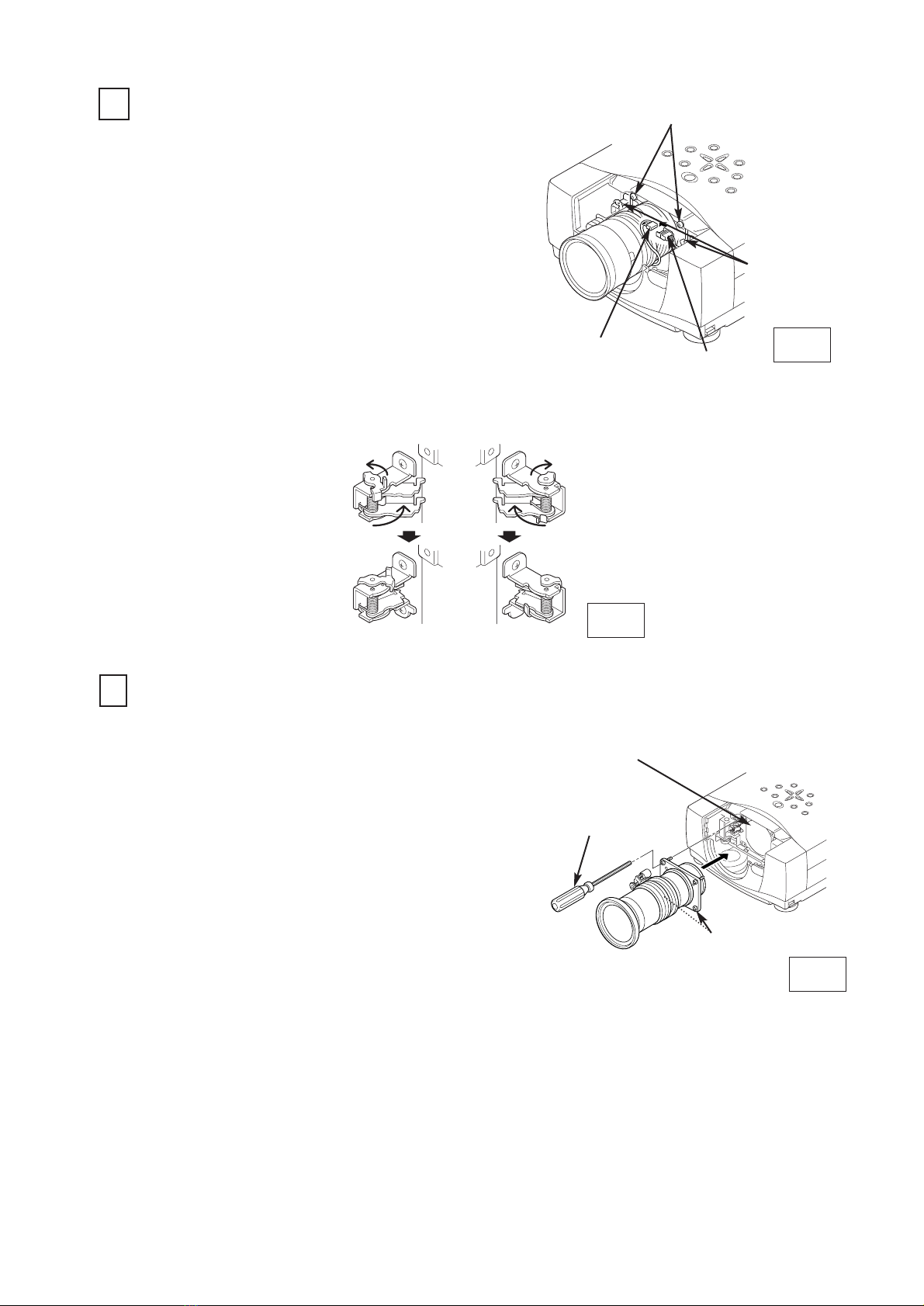
4MOUNT THE LENS (See Figure-5)
Remove protective caps (front and back) on the
lens.
Mount the lens on lens mounting bracket with
Upper 2 screws. (locate motor on left side).
Use the driver (4 mm, Yellow) included with the
lens to fasten the screws.
Remove the lower 2 screws on the Lens. (Lower 2
screws are not used.)
Slide the lens lock latches to "LOCK" position and
lock the lens. (See Figure-4)
Connect the lens motor connector to terminal.
(See Figure-3)
1.
2.
3.
4.
DRIVER
IN THE LENS
LENS MOUNTING
BRACKET
Fig-5
Fig-3
SCREW "B"
LENS LOCK
LATCHES
CONNECTOR
3REMOVE THE LENS (See Figure-3 and 4)
Remove the lens motor connector from terminal.
Loosen the screws-B (2 screws) which fastens
the lens. {Use the driver (4 mm, Yellow) included
with the lens to loosen the screws.}
Slide the lens lock latches to "UNLOCK" position
and remove the lens.
1.
2.
Be careful not to drop the lens when removing the
screws. After using, save the driver for latter use.
3.
TERMINAL
LENS LOCK LATCHES
LOCK
POSITION
UNLOCK
POSITION
Fig-4
LOWER SCREWS
-5-
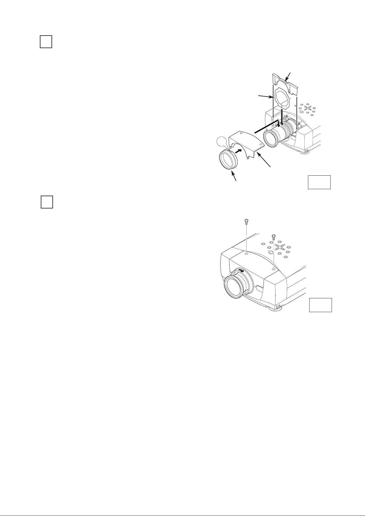
5MOUNT THE LIGHT-BLOCK SHEET AND
LIGHT-BLOCK SHEET BASE (See Figure-6)
6MOUNT THE FRONT CABINET AND LENS
COVER (See Figure-6 and 7)
Mount the light-block sheet on the lens as shown
in the Figure-6. (In the same position as the
removed sheet has been placed). Use the sheet
included with the lens.
Make sure the part no. and mark (TOP and BACK)
on Light-Block Sheet and set them properly.
Mount the light-block sheet base included with the
lens.
1.
2.
3.
UP
LIGHT-BLOCK
SHEET BASE
FRONT
CABINET
LENS COVER
LIGHT-BLOCK
SHEET
Mount the front cabinet with 2 screws.
Mount the lens cover.
For the cabinet Fig. 1-1, position the marked UP of
Lens Cover on top and push in to the front cabinet
and turn the Lens Cover fully clockwise until it is
properly locked.
For the cabinet Fig. 1-3, push the Lens Cover onto
the cabinet
1.
2.
Fig-7
-6-
Fig-6
- 7 -
Turn the lens cover to counter-clockwise and pull it
toward front and remove the Lens Cover.
Remove 2 Screws-A.
Remove the front cabinet
REMOVE THE LENS COVER AND
FRONT CABINET
1
1.
2.
2REMOVE THE LIGHT-BLOCK SHEET BASE
AND LIGHT-BLOCK SHEET
Perform the steps to for lens replacement.
16
First set the lens at the fully lower position with lens
shift adjustment.
3.
Slide the light-block sheet base upward and
remove it.
Remove the light-block sheet from lens.
1.
2.
LIGHT-BLOCK
SHEET BASE
FRONT
CABINET
LENS COVER
LIGHT-BLOCK
SHEET
SCREW "A"
LENS COVER
FRONT CABINET
3REMOVE THE LENS
Grasp the Lens Lock Lever and turn it fully
upward. Remove the Lens into the projector.
Disconnect the lens motor lead connector to the
socket on the lens attachment.
Remove 4 Screws and remove lens attachment.
1.
2.
3.
LENS
ATTACHMENT
SOCKET
CONNECTOR
LENS MOTOR
LEAD
LENS LOCK
LEVER
SCREW
Pull the Lens
Lock Lever
upward
LENS REPLACEMENT PROCEDURE (FOR "C" TYPE )

- 8 -
LENS
ATTACHMENT
Part No. (610 275 6029)
4MOUNT THE LENS
Remove protective caps (front and back) on the optional lens.
Mount the lens on the lens attachment with 4 Screws.
Connect the lens motor lead connector to the socket on the lens attachment. (Motor Driven
Lens only.)
Grasp the Lens Lock Lever and turn it fully upward. Install the Lens into the projector. Turn
the Lens Lock Lever fully downward until lever is Locked (clicked position) properly.
When installing the Motor Driven Lens, be sure to mount Lens Motor on left-side.
After installing the lens, make sure the Lens is not loose and properly installed.
1.
2.
3.
4.
Push the Lens
Lock Lever fully
downward until it is
locked (clicked).
DRIVER
IN THE LENS LENS
ATTACHMENT
SOCKET
CONNECTOR
LENS MOTOR
LEAD
LENS LOCK LEVER
LENS LOCK LEVER
SCREW
When the lens is attached to the projector and
images are being projected onto the screen, the
peripheral focus may be out of focus in some
localized areas. If this happens, insert the spacer
in between the lens attachment and the lens to
correct the focus.
Correcting the focus
Spacer "1"
Color; Clear
Thickness; 0.1 mm
40-inch projection
Screen
Inserting the spacers corrects the distance for best
diagonal focus at the screen.
The corrected distance is determined by the
thickness of the spacers that are used. As a guide,
the distance is adjusted by approximately 30 mm
for each 0.1-mm thickness of the spacers.
There are three types of spacers provided, and
there are four of each spacer type. Use these
spacers to correct the distance as required.
C
D
A
B
Distance
Spacer "2"
Color; Black
Thickness; 0.2 mm
Spacer "1"
Color; Cream
Thickness; 0.3 mm
Correction distance
30 mm/for 40-inch
projection
Correction distance
55 mm/for 40-inch
projection
Correction distance
80 mm/for 40-inch
projection
SPACER AB
C
D
A~D
Insertion position
of the focus
correction spacers.
Refer to following.
Insert spacers in
the location A~D
(above figure)
corresponding to
the screen location
A~D.
Screen

- 9 -
UP
5MOUNT THE LIGHT-BLOCK SHEET AND
LIGHT-BLOCK SHEET BASE
6MOUNT THE FRONT CABINET AND LENS
COVER
Mount the light-block sheet on the lens. (In the same
position as the removed sheet has been placed). Use
the sheet included with the lens.
Make sure the mark (TOP and BACK) on Light-Block
Sheet and set them properly.
Mount the light-block sheet base included with the
lens.
1.
2.
LIGHT-BLOCK
SHEET BASE
FRONT
CABINET
LENS COVER
LIGHT-BLOCK
SHEET
Mount the front cabinet with 2 screws.
Mount the lens cover.
Position the marked UP of Lens Cover on top and
push in to the front cabinet and turn the Lens Cover
fully clockwise until it is properly locked.
1.
2.

液晶プロジェクターレンズ
品番 LNS-T31A/W31A/T32
レンズ交換作業手順書
交換作業上の注意
レンズ交換はサ−ビス技術員が行ってください。
レンズ交換はこの作業手順書に従い、正しく行ってください。
レンズ交換のまえに、液晶プロジェクターの品番と交換レンズの品番をよく確
認のうえ、正しい品番のレンズをご使用ください。
レンズにはレンズ保護のためのキャップが付いています。レンズを取り付ける
まえに、かならずキャップを外してください。
レンズの取り付け、取り外しのとき、レンズ表面を手でさわったり傷を付けた
りしないようご注意ください。
適合レンズの詳しくは取扱販売店にご相談ください。
部品明細
梱包にはつぎの部品が入っています。
・レンズ本体
・遮光プレートベース
・専用ドライバー (3mm、 緑色)
・専用ドライバー (4mm、 黄色)
・遮光板 (LNS-T31A用)
(LNS-W31A用)
(LNS-T32用)
1AA6P1P3188A-(ICYDA-A)
1個
1個 (品番 6103108001)
1本 (品番 6102877328)
1本 (品番 6102756029)
1枚 型番 PB1(品番 6103107950)
1枚 型番 PC1(品番 6103107967)
1枚 型番 PF1(品番 6103107974)
安全のため、必ずつぎの点検と確認を行ってください。
レンズ交換のあと、キャビネットを組み立てるまえに、つぎの点検を行ってくだ
さい。
1.レンズがしっかり固定されているか。
2.配線が正しく行われているか、また配線の整形が正しく行われているか。
3.各接続コネクターは、しっかりはまっているか。
4.配線がレンズモーターのギヤーおよびその他のメカ部品にからまっていないか。
5.外れている部品はないか。
注意;このレンズはキャビネットの形状およびレンズ取り付け部によって取り付け
方法が異なります。(Aタイプ、Bタイプ、Cタイプ)
はじめにキャビネットの形状およびレンズ取り付け部をお確かめください。
This manual suits for next models
2
Table of contents
Other Fisher Projector manuals

Fisher
Fisher PLC-XP50L User manual

Fisher
Fisher PLC-XU30 User manual

Fisher
Fisher PLC-XU33 User manual

Fisher
Fisher PLC-XP41 User manual

Fisher
Fisher PLC-SU51 User manual

Fisher
Fisher PLC-XP40 User manual

Fisher
Fisher PLV-75 User manual

Fisher
Fisher LNS-T01Z User manual

Fisher
Fisher PLC-SU22N User manual

Fisher
Fisher LNS-T03 User manual

Fisher
Fisher PLC-SU70 User manual

Fisher
Fisher PLC-XP40L User manual

Fisher
Fisher PLC-XU47 User manual

Fisher
Fisher PLC-SW20 User manual

Fisher
Fisher PLC-XU31 User manual

Fisher
Fisher PLC-XU10N User manual

Fisher
Fisher PLC-XU07N User manual

Fisher
Fisher PDG-DSU20N User manual

Fisher
Fisher PLC-XP46 User manual

Fisher
Fisher PLC-XP17N User manual