Epson ELPMBP01 Guide
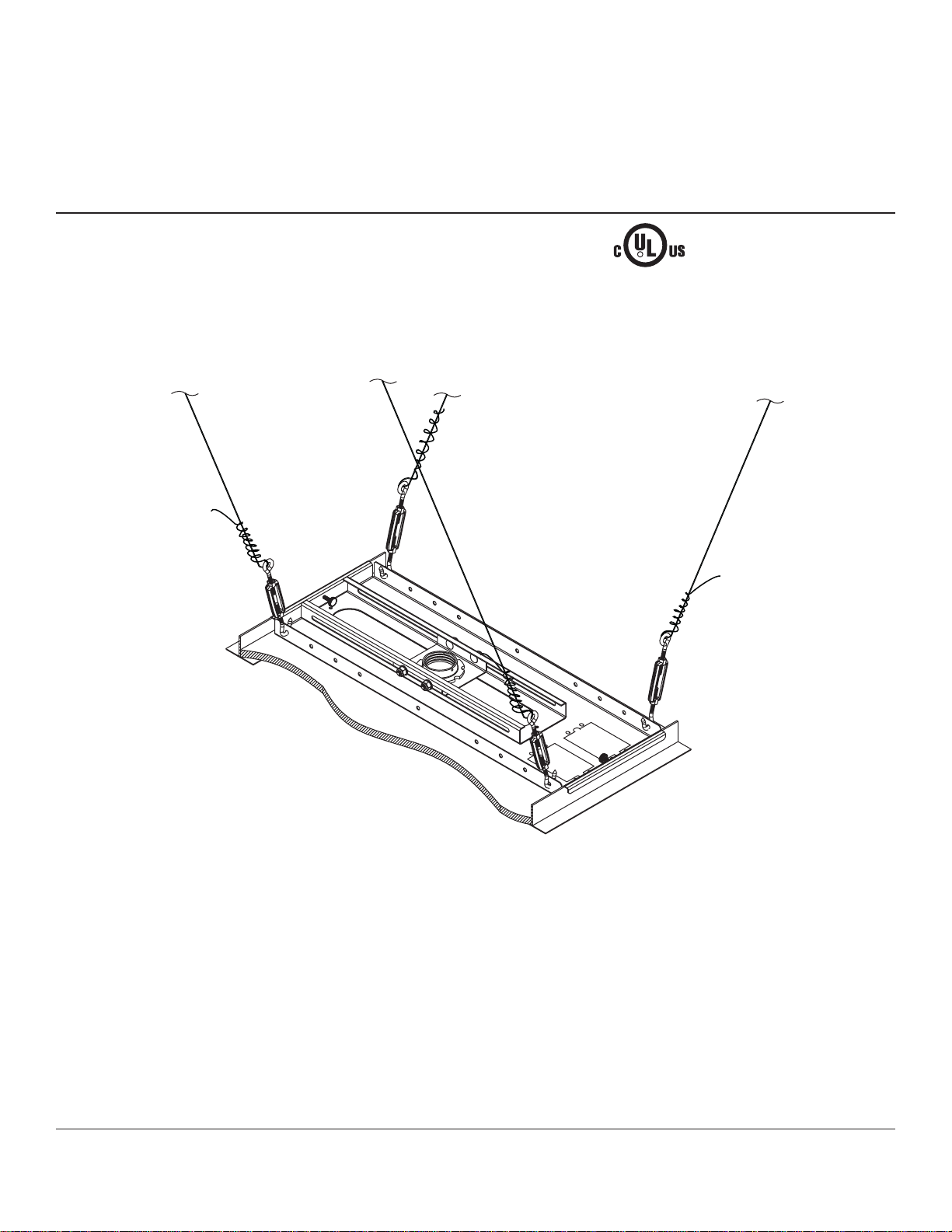
Model: ELPMBP01
3215 W. North Ave. • Melrose Park, IL 60160 • (800) 865-2112 or (708) 865-8870 • Fax: (708) 865-2941 • www.peerlessmounts.com
Maximum UL Load Capacity: 50 lb (22.6 kg)
This product is UL Listed. It must be
installed by a qualified professional
installer.
R
Installation and Assembly:
Adjustable Suspended Ceiling Channel Kit
Manufactured by Peerless Industries, Inc.

ISSUED: 02-13-08 SHEET #: 128-9029-2 07-10-08
2 of 6
Visit the Peerless Web Site at www.peerlessmounts.com For Technical Support Contact Peerless Mounts at 1-800-729-0307 or 708-865-8870.
Table of Contents
Parts List..............................................................................................................................................................................3
InstallationtoSuspendedCeiling ..........................................................................................................................................4
AnchoringCeilingPlate.........................................................................................................................................................5
WarrantyInformation.............................................................................................................................................................6
Tools Needed for Assembly
•studfinder("edgetoedge"studfinderisrecommended)
•phillipsscrewdriver
•hammer
•wire cutters
•drill
•1/4" bit for concrete surface
•5/32" bit for wood studs
NOTE: Read entire instruction sheet before you start installation and assembly.
• Do not begin to install your product until you have read and understood the instructions and warnings contained in this
InstallationSheet.Ifyou have any questions regarding any of the instructions or warnings, call Peerless customer care
at1-800-729-0307.
• This product should only be installed by someone of good mechanical aptitude, has experience with basic building
construction, and fully understands these instructions.
• Makesurethatthesupportingsurfacewillsafelysupportthecombinedloadoftheequipmentandallattachedhard-
wareand components.
• Neverexceedthe Maximum ULLoadCapacity.
• Always use an assistant or mechanical lifting equipment to safely lift and position equipment.
• Tighten screwsfirmly, but do notovertighten.Overtightening can damage the items,greatlyreducing their holding
power.See suggestedtorquevalues where applicablewithinthese instructions.
• Thisproductisintendedforindooruseonly.Useofthisproductoutdoorscould lead to product failure and personal
injury.
• When installing or adjusting the ceiling mount, do not use adhesives, lubricants or oils to prevent the screws from
loosening. If you use adhesives, lubricants, or oils to prevent the screws from loosening, the casing may crack and the
projector may fall, causing serious injury and damage to the projector.
WARNING
ISSUED: 02-13-08 SHEET #: 128-9029-2 07-10-08
3 of 6
Visit the Peerless Web Site at www.peerlessmounts.com For Technical Support Contact Peerless Mounts at 1-800-729-0307 or 708-865-8870.
D
A
E
L
BC
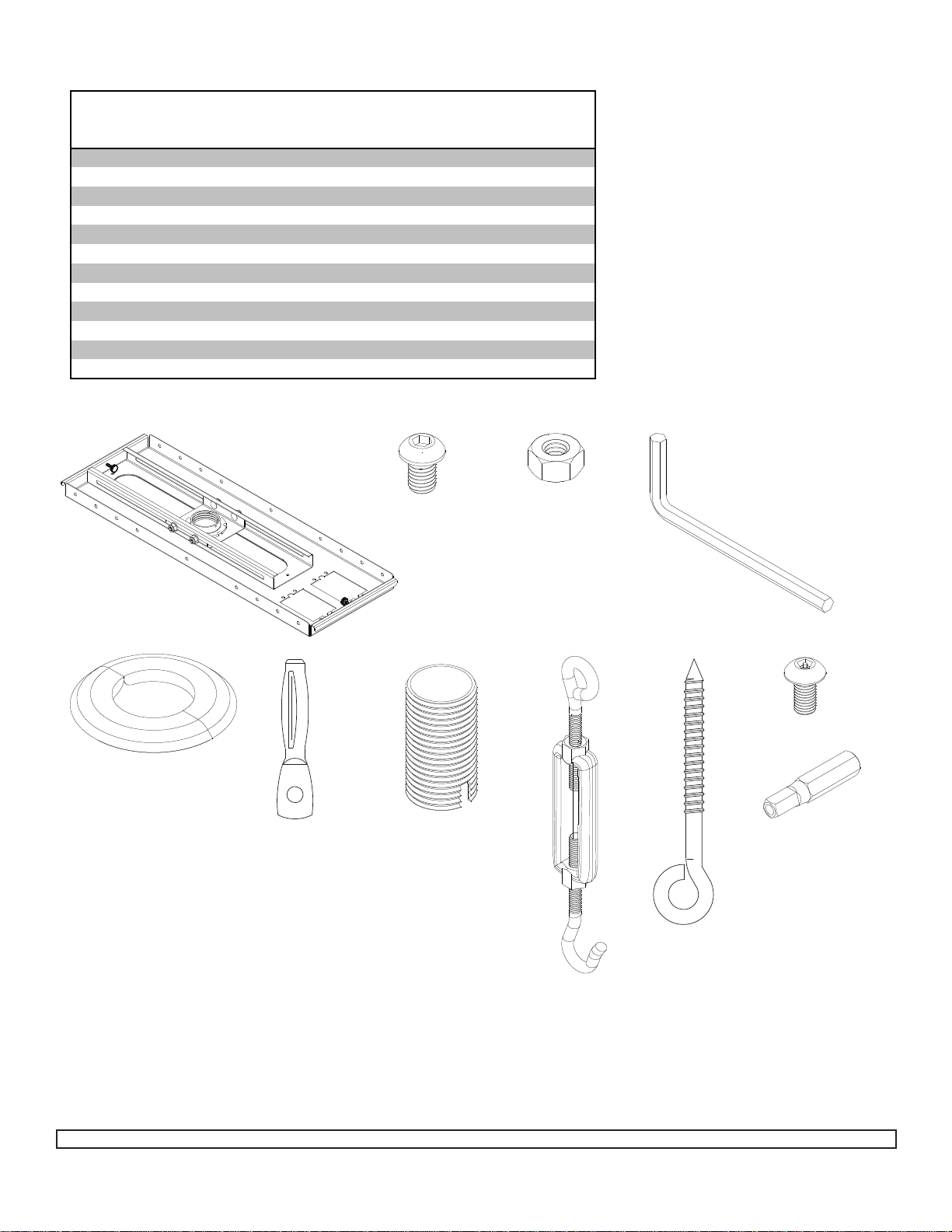
Before you start check the parts list to insure all of the parts shown are included.
NOTE:Youmaynot need all hardware provided.
NOTE: Somepartsmayappearslightlydifferentthanillustrated.
IHFJ K
Description
Q
t
y.
Part #
A
ceiling tray 1055-0492
B1/4"-20 x 3/8" screws 4 520-2015
C1/4"-20 nuts 4 530-9302
Dallen wrench 1 560-9706
Eescutcheon ring 1 1418-001A
Fturnbuckle 4 560-9620
G12 gauge x 20' (6.1m) tie wire (not shown) 1 600-2008
Heye bolt 5 580-0006
Iconcrete anchor 5 580-0005
Jflush mount tube 1 1446-014
KM5 x 10 mm penta pin screw 1 505-9010
LM5 x 1" penta pin driver 1 520-9249
Parts List
ISSUED: 02-13-08 SHEET #: 128-9029-2 07-10-08
4 of 6
Visit the Peerless Web Site at www.peerlessmounts.com For Technical Support Contact Peerless Mounts at 1-800-729-0307 or 708-865-8870.
IMPORTANT PRE-ASSEMBLY
INFORMATION:
Ceiling Tray (A) is designed to fit
abovea24"(610 mm) x 24" (610
mm)section of a conventional
suspended ceiling system. It may
alsobemountedabove24"x48"
conventionalsuspended ceiling.
Ceilingrunners (see DETAIL2,
page 5) should have a “T” cross
section and a minimum height of
1.5" (38 mm).
For certain installations it may be
best to install ceiling anchors (step
5) beforeinstallingtheceilingtray
(step1).
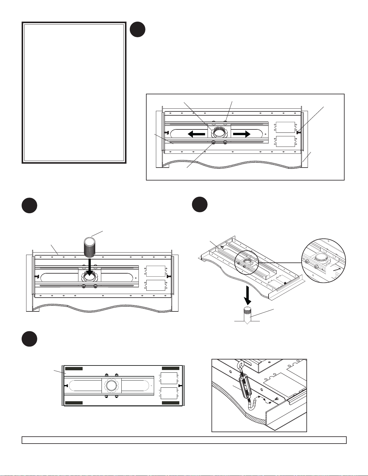
Place ceiling tray (A) in grid above 24" x 24" or 24" x 48" false ceiling tile
so that lip of ceiling tray (A) rests on ceiling runners as shown in figure 1.
Place in desired position and tighten knurled knobs until ceiling tray (A) is
securely attached to ceiling runners.
Slide collar mount plate to desired position. Using hole in collar mount
plate, mark false ceiling tile where hole will be cut. Slide collar mount plate
out of the way. Cut out 2.25" hole in false ceiling tile. Slide collar mount
plate back into position and tighten all carriage bolts and nylock nuts using
a7/16" wrench.
A
CEILING
RUNNER
COLLARMOUNTPLATE KNURLEDKNOB
CARRIAGEBOLT
NYLOCKNUT
Fromthetop down, thread flush mount tube (J)down
throughretainingcollarinadjustablecollar mount
plate.
Skip to step 3. J
For Flush MountingApplications From the bottom up, thread extension column (not
included)upthroughretaining collar in adjustable
collar mount plate.Align notch in extension
column with hole in collar and fasten using M5 x
10 mm security screw (K) as shown in detail 1.
For Extension Column Applications
TOP VIEW - CEILING TRAY
Blackrectangles showcorrect
positionsfor Turnbuckles.
Snap escutcheon ring (E) around flush mount tube or extension column and slide up until flush with ceiling tile. Hook
turnbuckles (F) into ceiling tray (A) as shown in figure 2. Hook turnbuckles through ceiling tray (A) where indicated
by black rectangles in illustration below.
F
A
11/2"EXTENSIONCOLUMN
(SOLDSEPARATELY)
(ULLISTEDEXTORADJSERIES)
K
AA
1
22
3
Installation to Suspended Ceiling
fig. 1
fig. 2
DETAIL 1

ISSUED: 02-13-08 SHEET #: 128-9029-2 07-10-08
5 of 6
Visit the Peerless Web Site at www.peerlessmounts.com For Technical Support Contact Peerless Mounts at 1-800-729-0307 or 708-865-8870.
Cut tie wire (G)into four pieces of equal length. Insert wires through ends of turnbuckles and loop. Twist each wire
around itself at least six times.
Drill holes for four ceiling anchors (see "VariousAnchoring Methods"). Position the holes so that when the tie
wires (G) are attached and taut will angle out at 15O.
Pull tie wires tight and loop though turnbuckles of the ceiling anchors (or truss). Again twist each wire around itself
at least six times.
When this step is complete, the weight of the ceiling tray should be supported by the tie wires.
NOTE: 20' (6.1 m) of tie wire (G) is provided. If space between the true ceiling and suspended ceiling is more than
36"(914 mm), additional wire (12 gauge annealed, steel, black) will be needed.
SuspendedCeilingKit installation is nowcomplete.
Afterall components(Projector Mount,Extension
Column,etc.)andequipmenthavebeenattached,
tension the tie wires by adjusting turnbuckles (F).
NOTE: Load must be carried by tie wires - not
suspendedceiling runners.
A
GG
G
CEILING
RUNNER
KNOCK-OUTSARE
PROVIDEDFOR
ELECTRICAL OUTLET
BOXESANDANTENNA
LEADS.
2"
15°
1.5"
4
5
VARIOUSANCHORINGMETHODS
Wood Joists or Beams
Drill5/32"(4mm)dia.
holes2"(51mm) deep.
Fully insert eye bolts (H).
Solid Concrete
Drill 1/4" (6 mm) dia. holes 1.5" (38 mm)
deep. HammerinConcreteAnchor(I)
usingRawl#3250 setting tool
orequivalent.
HI
Truss Ceiling
Noanchor required. After
attaching tie wire to turnbuckle
loopupper endaroundceiling
truss. Pull tie wire tight and
twist it around itself at least six
times.
Anchoring Ceiling Plate
DETAIL 2
• It is the responsibility of the installer to verify that the
ceiling to which the suspended ceiling kit is anchored
willsafelysupportfourtimesthecombined weight of
allattachedcomponents(Projector Mount, Extension
Column,etc.)and equipment.
WARNING

ISSUED: 02-13-08 SHEET #: 128-9029-2 07-10-08
6 of 6
Visit the Peerless Web Site at www.peerlessmounts.com For Technical Support Contact Peerless Mounts at 1-800-729-0307 or 708-865-8870.
3HHUOHVV,QGXVWULHV,QFHVWDEOLVKHVDZDUUDQW\SHULRGRIÀYH\HDUVIRUSURGXFWVPDQXIDFWXUHGRUVXSSOLHGE\3HHUOHVV7KLVSHULRGFRPPHQFHVIURPWKHGDWH
RIVDOHRIWKHSURGXFWWRWKHRULJLQDOFRQVXPHUEXWZLOOLQQRFDVHODVWIRUPRUHWKDQVL[\HDUVDIWHUWKHGDWHRIWKHSURGXFWҋVPDQXIDFWXUH'XULQJWKHZDUUDQW\
SHULRGVXFKSURGXFWVZLOOEHIUHHIURPGHIHFWVLQPDWHULDODQGZRUNPDQVKLSSURYLGHGWKH\DUHLQVWDOOHGDQGXVHGLQFRPSOLDQFHZLWKWKHLQVWUXFWLRQVHVWDEOLVKHGE\
3HHUOHVV,QGXVWULHV,QF6XEMHFWWRDSSOLFDEOHOHJDOUHTXLUHPHQWVGXULQJWKHZDUUDQW\SHULRG3HHUOHVVZLOOUHSDLURUUHSODFHRUUHIXQGWKHSXUFKDVHSULFHRIDQ\
VXFKSURGXFWZKLFKIDLOVWRFRQIRUPZLWKWKLVZDUUDQW\
$Q\RWKHUZDUUDQWLHVSUHVFULEHGE\WKHODZZKLFKPD\DSSO\ZLWKUHVSHFWWRVXFKSURGXFWVDOVRDUHOLPLWHGLQGXUDWLRQWRWKHZDUUDQW\SHULRGVSHFLÀHGLQWKLV/LPLWHG
)LYH<HDU:DUUDQW\
7KLVZDUUDQW\GRHVQRWFRYHUGDPDJHFDXVHGE\DVHUYLFHRUUHSDLUVE\WKHFXVWRPHURUDSHUVRQZKRLVQRWDXWKRUL]HGIRUVXFKVHUYLFHRUUHSDLUVE\3HHUOHVV
,QGXVWULHV,QFEWKHIDLOXUHWRXWLOL]HSURSHUSDFNLQJZKHQUHWXUQLQJWKHSURGXFWFLQFRUUHFWLQVWDOODWLRQRUWKHIDLOXUHWRIROORZ3HHUOHVVҋLQVWUXFWLRQVRUZDUQLQJV
ZKHQLQVWDOOLQJXVLQJRUVWRULQJWKHSURGXFWRUGPLVXVHRUDFFLGHQWLQWUDQVLWRURWKHUZLVHLQFOXGLQJLQFDVHVRIWKLUGSDUW\DFWLRQVDQGIRUFHPDMHXUH
,QQRHYHQWVKDOO3HHUOHVVEHOLDEOHIRULQFLGHQWDORUFRQVHTXHQWLDOGDPDJHVRUGDPDJHVDULVLQJIURPWKHWKHIWRIDQ\SURGXFWZKHWKHURUQRWVHFXUHGE\DVHFXULW\
GHYLFHZKLFKPD\EHLQFOXGHGZLWKWKHSURGXFW
7KLV/LPLWHG)LYH<HDU:DUUDQW\LVLQOLHXRIDOORWKHUZDUUDQWLHVH[SUHVVHGRULPSOLHGDQGLVWKHVROHUHPHG\ZLWKUHVSHFWWRSURGXFWGHIHFWV1RUHWDLOHUGHDOHU
GLVWULEXWRULQVWDOOHURURWKHUSHUVRQLVDXWKRUL]HGWRPRGLI\RUH[WHQGWKLVZDUUDQW\RULPSRVHDQ\REOLJDWLRQRQ3HHUOHVVLQFRQQHFWLRQZLWKWKHVDOHRIDQ\SURGXFW
PDQXIDFWXUHGRUVXSSOLHGE\3HHUOHVV
7KLVZDUUDQW\JLYHVVSHFLÀFOHJDOULJKWVDQG\RXPD\DOVRKDYHRWKHUULJKWVSURYLGHGE\WKHQDWLRQDOOHJLVODWLRQRIWKHFRXQWU\LQZKLFK\RXSXUFKDVHGVXFKSURGXFW
LIMITED FIVE-YEAR WARRANTY
© 2007 Peerless Industries, Inc.
www.peerlessmounts.com
ISSUED 03/17/06 LIT-0190E
©2008,PeerlessIndustries,Inc.Allrights reserved.
Allother brand andproduct names aretrademarks or registeredtrademarks of theirrespective owners.
Table of contents
Other Epson Projector Accessories manuals

Epson
Epson EB-435W guide User manual

Epson
Epson ELPMB45 User manual

Epson
Epson ELPMB60 User manual

Epson
Epson ELPMB62 User manual

Epson
Epson ELPMB27 Operating and safety instructions

Epson
Epson ELPMBC01 Guide

Epson
Epson Panamorph ELPALK2 User manual

Epson
Epson ELPWP20 User manual

Epson
Epson ELPBU01 User manual

Epson
Epson ELPLX01 User manual

Epson
Epson ELPMB29 User manual

Epson
Epson ELPMB27 User manual

Epson
Epson ELPWR01 User manual

Epson
Epson ELPLX03 User manual

Epson
Epson ELPLL07 User manual

Epson
Epson ELPMB44 User manual

Epson
Epson ELPMBPJF - Universal Projector Ceiling Mount Guide

Epson
Epson Duet User manual

Epson
Epson ELPMBP02 - False Ceiling Plate Guide

Epson
Epson ELPLX02S User manual