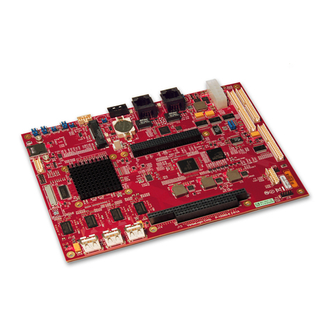
EMAC VDX3-6726 Series User manual

User Manual
VDX3-6726
with
DM&P Vortex86DX3
1GHz processor
Version 2.0

VDX3-6726 User Manual
I
Copyright
The information in this manual is subject to change without notice for
continues improvement in the product. All rights are reserved. The
manufacturer assumes no responsibility for any inaccuracies that may be
contained in this document and makes no commitment to update or to
keep current the information contained in this manual.
Trademarks Acknowledgement
Vortex86DX3TM is the registered trademark of DM&P Electronics Inc. Other
brand names and product names that appear in this document are the properties
and registered trademarks of their respective owners. All names mentioned
herewith are served for identification purpose only.

VDX3-6726 User Manual
II
Revision History
Revision Date Remark
1.0 June 13, 2016 First version release
2.0 June 8, 2017 New Add: Working temperature for Dual Core version

VDX3-6726 User Manual
III
Table of Contents
1 General Information ........................................................................................................................ 1
1.1 Overview ........................................................................................................................................... 1
1.2 Block diagram ................................................................................................................................... 1
1.3 Specifications .................................................................................................................................... 2
1.4 Ordering Information ..................................................................................................................... 4
1.4.1 VDX3-6726 ................................................................................................................................ 4
1.4.2 Cable Set ..................................................................................................................................... 4
1.4.3 SATA DOM .............................................................................................................................. 5
2 Hardware Information ..................................................................................................................... 6
2.1 Dimension ......................................................................................................................................... 6
2.2 Board Outline ................................................................................................................................... 7
2.3 Connector and Jumper Summary .................................................................................................. 8
2.4 Pin Assignments & Jumper Settings ............................................................................................. 9
J1: LCD ................................................................................................................................................ 9
J2: LVDS (24 bits) .............................................................................................................................. 9
J3: VGA ............................................................................................................................................... 9
J4: SATA DOM ................................................................................................................................ 10
J6: DC 5V output.............................................................................................................................. 10
J7: REST ............................................................................................................................................ 10
J8: GPIO (Port 0/1) ......................................................................................................................... 10
J9: LAN 1 (RJ45) .............................................................................................................................. 10
J10: LAN 2 ......................................................................................................................................... 10
J11: LAN 3 ......................................................................................................................................... 10
J12: USB2 ........................................................................................................................................... 10
J13: USB0&1 ..................................................................................................................................... 11

VDX3-6726 User Manual
IV
J14: USB3&4 ..................................................................................................................................... 11
J15: COM1 ......................................................................................................................................... 11
J17: COM2 ......................................................................................................................................... 11
J18: COM3 ......................................................................................................................................... 11
J18: COM4 ......................................................................................................................................... 11
J20A: PC/104 Connector – 64 pin ................................................................................................ 12
J20B: PC/104 Connector – 40 pin ................................................................................................. 12
J21: DC power output...................................................................................................................... 13
J23: Line-out ...................................................................................................................................... 13
J24: MIC-in ........................................................................................................................................ 13
J25: Touch screen connector .......................................................................................................... 13
J26: Parallel ........................................................................................................................................ 13
J27: Power Connector ...................................................................................................................... 13
System Mapping .................................................................................................................................. 1
3 Software Resources......................................................................................................................... 14
3.1 Technical Resource Website .......................................................................................................... 14
4 Technical support ........................................................................................................................... 14
4.1 Display Introduction ...................................................................................................................... 14
4.2 BIOS Introduction ......................................................................................................................... 14
4.2.1 CPU Clock Adjusting ............................................................................................................. 14
4.2.2 Console Direction ................................................................................................................... 15
4.2.3 Serial Ports Switching ............................................................................................................. 16
4.2.4 IDE Configuration ................................................................................................................. 17
4.2.5 Advanced Configuration ........................................................................................................ 18
4.2.6 ACPI Enable ........................................................................................................................... 19
5 Basic LCD Panel Setting ................................................................................................................ 20
5.1 Introduction .................................................................................................................................... 20

VDX3-6726 User Manual
V
5.2 Basic BIOS Setting for LCD ...................................................................................................... 21
Technical Support Directly ...................................................................................................................... 23
User Manual Feedback ............................................................................................................................. 23
Appendix .................................................................................................................................................... 24
Stacking Solution for Daughter Board .............................................................................................. 24
Warranty ..................................................................................................................................................... 25

VDX3-6726 User Manual
1
1 General Information
1.1 Overview
The VDX3-6726 family of low-power x86 embedded controller is designed to
meet 3.5” specification with backward compatibility to provide migration path for
projects facing end-of-life challenges with their existing x86 based 3.5” controller.
In addition, the VDX3-6726 family of controller is designed as a plug in
replacement, with backward compatibility to support legacy software to help
extend existing product life cycle without heavy re-engineering.
The VDX3-6726 is suitable for broad range of data-acquisition, industrial
automation, process control, automotive controller, AVL, intelligent vehicle
management device, medical device, human machine interface, robotics, machinery
control and more
1.2 Block diagram

VDX3-6726 User Manual
2
1.3 Specifications
Processor DM&P SoC CPU Vortex86DX3 - 1GHz
L1:32K I-Cache, 32K D-Cache, L2 Cache:512KB
RAM 1GB/2GB DDR3 Onboard
BIOS AMI BIOS
Bus PC/104 Standard Compliant
Display
Integrated 2D VGA chip with dual display support
(VGA +TTL / VGA + LVDS )
VGA: Maximum resolution up to 1920x1080 @ 60Hz
LVDS: Maximum resolution up to 1024x768 @ 60Hz
Single channel 24-bit LVDS
LAN Integrated 10/100Mbps Ethernet x1
Realtek 8111F GbE x2
I/O Interface
RS232 x4
Parallel x1
DOS hot SWAP x1 (Optional)
HD Audio
USB (ver. 2.0) x4
16-bit GPIO x1
PS/2 touch controller x1 (Optional)
Connectors
2.54mm 4-pin pin header for DC output x1
2.54mm 2-pin pin header for Reset x1
2.54mm 104-pin PC/104 connector x1
2.0mm 44-pin box header for LCD x1
2.0mm 26-pin box header for Parallel x1
2.0mm 20-pin pin header for 16-bit GPIO x1
2.0mm 20-pin pin header for LVDS x1
2.0mm 10-pin box header for USB x2
2.0mm 10-pin box header for RS232 x4
2.0mm 8-pin pin header for Ethernet x1
2.0mm 8-pin pin header for GbE x1
1.25mm 4-pin wafer connector for Line-out/MIC-in x2
2-pin box header for DC 5V output x1
7-pin SATA connector for SATA DOM x1
RJ45 connector for GbE x1
15-pin D-Sub female connector for VGA x1
9-pin D-Sub male connector for RS232 x1
PS/2 connector for Keyboard/Mouse x1

VDX3-6726 User Manual
3
Power
Requirement DC +5V @1300mA (Typical)
Operating Temp.
-20C ~ +70°C (Single Core)
-10°C ~ +60°C (Dual Core)
-40°C ~ +85°C (Optional for Single Core)
-20°C ~ +70°C (Optional for Dual Core)
Dimensions 102mm x 146mm
Weight 150g
O/S Support
Windows 7
Windows Embedded Standard 7
Windows Embedded Compact 7
Windows Embedded CE6.0
Windows XP Professional
Windows Embedded 2009
Linux
DOS
POS Ready (WePOS)
QNX
VxWorks
Free BSD

VDX3-6726 User Manual
4
1.4 Ordering Information
1.4.1 VDX3-6726
Product
Name
1GB DDR3
onboard
2GB DDR3
Onboard
Touch
Function
Dual
Core
VDX3-6726-1G V
VDX3-6726-2G V
VDX3-6726-2C-1G V V
VDX3-6726-2C-2G V V
VDX3-6726-1G-T V V
VDX3-6726-2G-T V V
VDX3-6726-2C-1G-T
V V V
VDX3-6726-2C-2G-T
V V V
CABLE-SET-6726
1.4.2 Cable Set
Product Name Contents
CABLE-SET-6726
NET4X2 (2.0) x2
RS232(2.0) x4
GPIO(2.0) x1
PRINT(2.0) x1
Audio Line x2
USB(2.0) x2
This manual suits for next models
8
Table of contents
Other EMAC Single Board Computer manuals