EliteProAV MT100XWH User manual

Rev.04/28/17 DR 1 www.eliteproav.com
Manual Tab-Tension Series
Tensioned Manual Pull Down Projector Screen
(Bead Chain Operated)
User’s Guide
Thank you for choosing the Manual Tab-Tension Series projection screen!
Please be sure to read the precautions and operating instructions carefully
before operating the screen. Proper maintenance and handling will ensure a
longer life-span of the product.
WARNING!
Keep the bead chain out of the reach of small children. A child can
accidentally hook the bead chain around his/her neck and cause serious
injury or even death.
1. ALWAYS keep cords and bead chains out of children’s reach.
2. MOVE cribs, playpens, beds, and any other furniture away from the
bead chain. Children can climb on furniture and be able to reach the chain.
3. INSTALL the chain tensioner as it serves as a safety device to keep the
bead chain from being able to be pulled away from the wall.
Note:
Wall screws included with this product are complementary and may not be adequate for all mounting
surfaces. Consult with a professional installer or hardware store for proper mounting screws and anchors.
Regardless of the mounting method, the screen should be securely supported so that the vibration or pulling
on the viewing surface will not cause the screen case to become loose or fall. The installer must ensure that
proper mounting hardware and the fasteners used are of adequate strength and suitable for the mounting
surface.

Rev.04/28/17 DR 2 www.eliteproav.com
Hardware Parts List
Please make sure all parts listed below are included before proceeding with the installation.
A. M5x60 Screw x4
B. M12 Dry-wall
anchor x4
C. Bracket connector x2
D. M5x25MM round head
cross screws x2 & M5 nut x2
E. M5x30MM eyebolt
screw & M5 nut x2
F. Hidden wall
bracket x2
G. R18xR6x1
washer x4
H. Snap link x2
I. Bead chain tensioner x1
J. M4x32 Screw x2&M8
Dry-wall anchor x2
Installation Instructions
For installation assistance, please consult a professional Installer. EliteProAV is not liable for faulty installations.
A. Wall Mount
Flush hidden mount (movable position)
This installation method allows the screen to slide horizontally.
1. Determine where the screen will be installed. Then, measure and mark the distance between the top and bottom screw
holes from each hidden wall mount bracket (F).
2. Drill a hole on all marked areas and install the brackets with the dry-wall anchor (B), M5x60 screw (A), and a washer (G).
Make sure both brackets are properly leveled.
3. Hang the screen by placing the downward “catch” located on the back over the brackets upper “catch”.
4. After making sure the screen is secured, you can slide it left / right to properly center it in position.
5. Lastly, screw the M5 screw (D) into the upper hole of the bracket to add additional support for the screen.
B. Ceiling Mount
Suspended
1. Screw the eyebolt (E) on the bracket connector (C).
2. Attach the snap link (H) through the eyebolt (E) and connect it to an eyebolt screw (not included) rated for the screen’s
weight.
Front view of bracket (F)
Side view of
bracket (F)

Rev.04/28/17 DR 3 www.eliteproav.com
Notice to Installer:
Please use the following installation instructions to obtain superior optical performance from the
CineGrey 5D® Angular Reflective ALR (Ambient Light Rejecting) Screen.
Make sure to follow these instructions in order for the CineGrey 5D® to perform correctly.
•Angular-Reflective material is not compatible with ultra/short-throw projectors
•Minimum lens throw ratio 1.5x image width
•Ambient light must not come from the same direction as the projector
Since angular-reflective means that the projected image will reflect at the mirror-
opposite angle, it is important to position the projector so that the viewer will get the best
possible image.
Step 1: Establish the general “eye level” of the viewers
Step 2: Set the appropriate projection level
Step 3: Adjust the screen height level and projection angle
Input Angle (A) = Output Angle (B) aligns with the viewer’s angle

Rev.04/28/17 DR 4 www.eliteproav.com
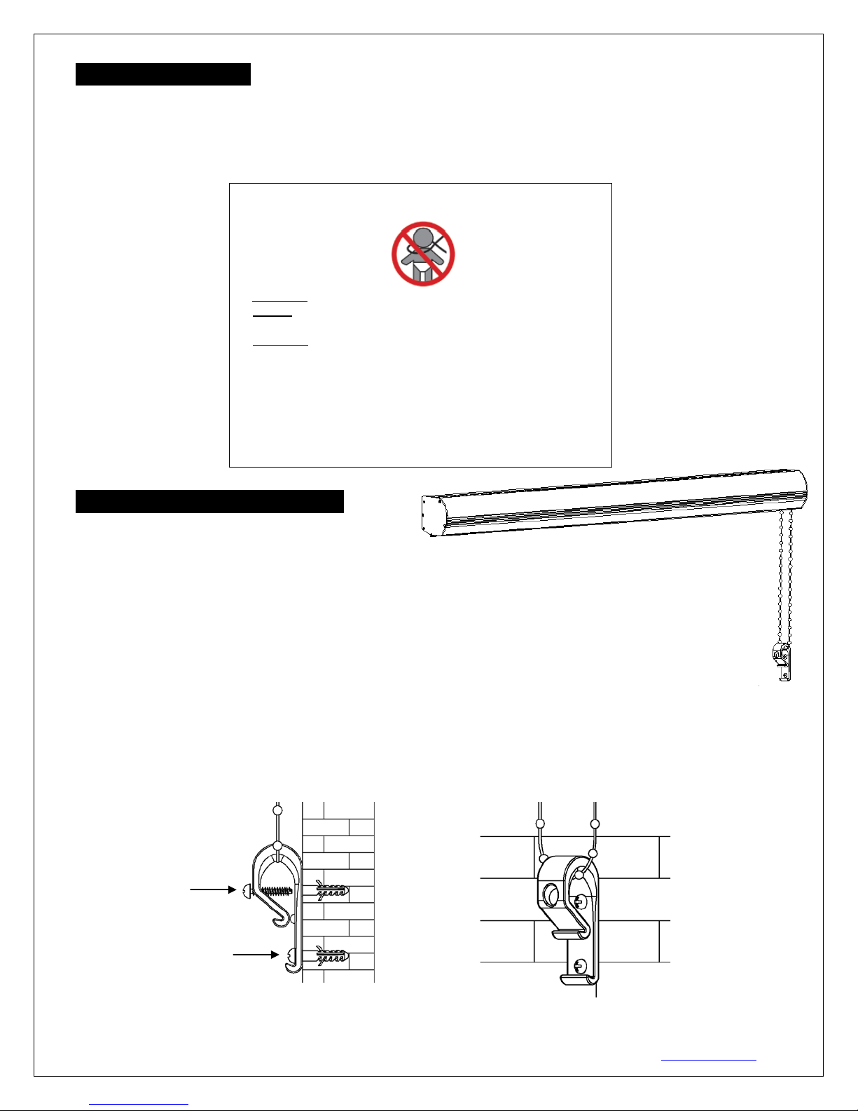
Bead Chain Tensioner1.
EliteProAV Manual Tab-Tension Series uses a Bead Chain Clutch Operated mechanism to allow the screen
material to roll down and up. For the safety of young children, it includes a Bead chain tensioner (I) device
pre-attached to the bead chain (along with the safety label below). To use this tension clip, thread bead chain
through the clip, then attach to wall or window sill so that the bead chain is held taut enough that children
cannot pull it away from the wall or fit their head into the loop.
Bead Chain Tensioner Installation
1. After the screen has been properly installed, allow the bead chain to hang down freely. Then find the best
place on your wall to attach the Bead chain tensioner (I).
2. After locating the position of the Bead chain tensioner (I), mark where to drill the holes for the anchors
with a pencil.
3. Drill the holes and insert the M8 Dry-wall anchor (J).
4. Tighten the M4x32 Screw (J) to the M8 Dry-wall anchor (J) when the upper hole of the Bead chain
tensioner (I) aligns with the hole of M8 Dry-wall anchor (J).
5. Tighten the bottom screw hole as shown below to complete the tensioner installation.
Warning for the Safety of Young Children
Young children can STRANGLE in cord and bead chain loops.
1. ALWAYS keep cords and bead chains out of children’s reach.
2. MOVE cribs, playpens, beds, and any other furniture away from the
bead chain. Children can climb on furniture and get to the cord loop.
3. INSTALL the bead chain tensioner as it serves as a safety device to
keep the bead chain from being able to be pulled away from the wall.
Fasteners provided with the tension device may not be appropriate for
all mounting surfaces. Use appropriate anchors to safely secure the
tension device to the mounting surface.

Rev.04/28/17 DR 5 www.eliteproav.com
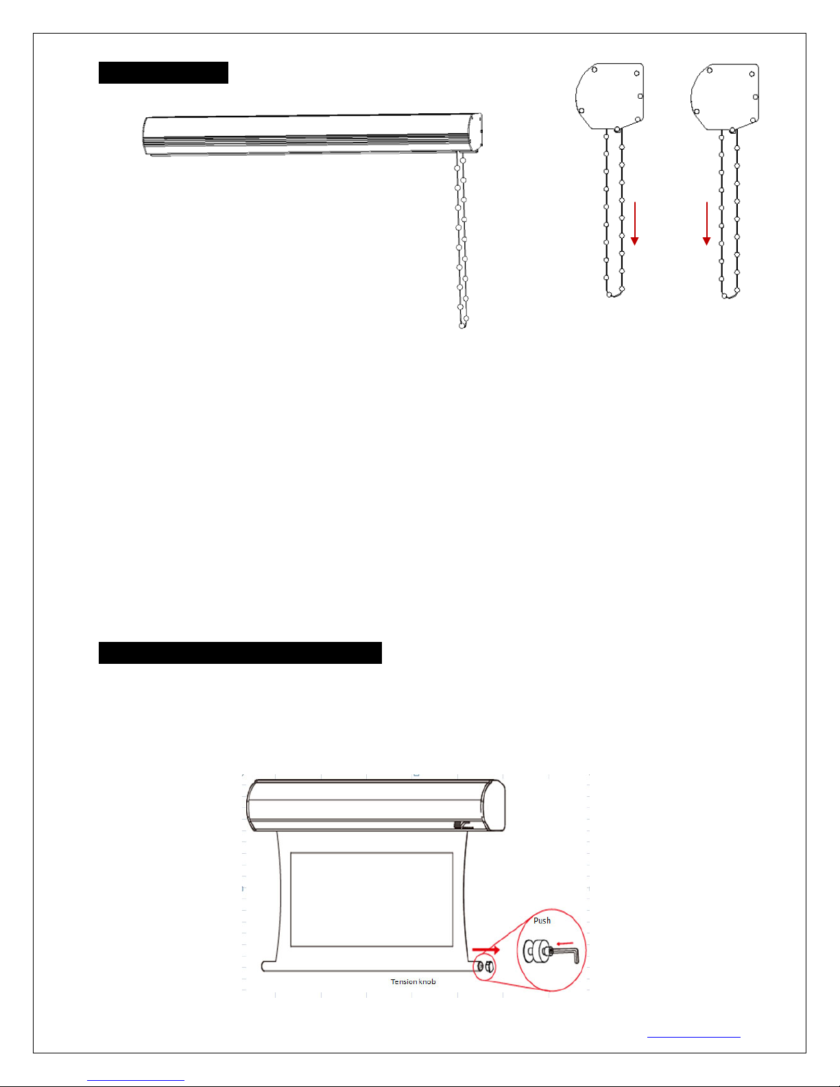
Screen operation
To lower the screen, grasp the bead chain length closest to the wall and pull downward.
To raise the screen, grasp the bead chain length furthest from the wall and pull downward.
Please note the following points to avoid reducing the life-span of the bead chain.
1. The chain should be pulled straight down. Do not to pull the chain in any angle outwards or to the sides.
In doing so, the chain will scratch the housing of the screen.
2. The chain should be pulled down in a constant motion. DO NOT pull and stop the chain rapidly to avoid
shaking and damaging the screen which can be dangerous if not properly fastened and secured.
3. When pulling down the screen with the chain, please note there is a limiting device on the bead chain to
keep the screen from rolling down too much. Bear in mind that the screen can deploy as far as indicated in
the spec sheet. DO NOT pull down on the bead chain any harder than needed to deploy and retract the
screen. Vigorous operation of the chain can cause damage to the unit.
4. Failure to follow these instructions will void your warranty.
Screen Material Tension Adjustment (4mm Allen Wrench required and not included)
Remove the weight bar end cap to expose the adjustment tension knob. Insert your 4mm Allen Wrench to
push in the adjustment tension knob, turn clockwise and your screen will gain more tension. Turn the Allen
Wrench counter clockwise and the screen will lose tension. Please note this adjustment is not necessary as
the tension of the screen has been set to its factory setting for best performance. Please contact
EliteProAV™ for assistance to avoid damaging the screen and voiding your warranty.
Screen down
Screen up

Rev.04/28/17 DR 6 www.eliteproav.com
Models A A1 A2 A3 A5 A4 B B1 B2 B3 B4 B5 C C1 C2 C3 C4
Unit: Inches
MT100XWH 104.8 87.2 73.3 96.9 4.8 101.7 68.3 49.0 63.4 12.0 2.4 4.4 4.6 4.9 1.4 0.9 66.1
MT113NWX 114.4 95.8 82.9 107.6 5.9 111.4 79.2 59.9 74.3 12.0 2.4 4.4 4.6 4.9 1.4 0.9 77.2
MT120XWV 114.4 96.0 82.9 105.7 4.9 111.4 91.3 72.0 86.4 12.0 2.4 4.4 4.6 4.9 1.4 0.9 89.4
Unit: mm
MT100XWH 2662 2214 1862 2460 123 2582 1735 1245 1610 305 60 112 118 125 35 23 1680
MT113NWX 2906 2434 2106 2732 149 2830 2011 1521 1886 305 60 112 118 125 35 23 1960
MT120XWV 2906 2438 2106 2686 124 2830 2319 1829 2194 305 60 112 118 125 35 23 2270
For more information, technical support or your local EliteProAV contact,
please visit www.eliteproav.com
Note Data Error: ±1"
Dimensions Table
This manual suits for next models
2
Table of contents
Other EliteProAV Projector Accessories manuals

EliteProAV
EliteProAV Pro Series User manual

EliteProAV
EliteProAV Yard Master Electric Series User manual

EliteProAV
EliteProAV WhiteBoardScreen TE CLR 2 Series User manual

EliteProAV
EliteProAV Pro Frame Thin DarkStar UST 2 Series User manual

EliteProAV
EliteProAV Tension Pro Series User manual

EliteProAV
EliteProAV CineGrey 5D User manual

EliteProAV
EliteProAV AV Yard Master Series User manual

EliteProAV
EliteProAV Tension Pro Series User manual