Eight RETRO RADIO User manual


Introducon
By assembling this radio, you will gain insights into electronics and experience a sense of achievement even early on. Explore
the funconality of the individual components and gradually build a complex circuit. Finally, use the completed FM radio to
listen to your local FM staon in great sound quality!
The FM radio is easy to
assemble and yet oers
many possibilies. There
are numerous versions
and opons. Feel free to
experiment with
dierent circuits and
antennae to receive
staons near you or far
away.
Enjoy your radio kit!
2

Contents
Introducon .................................................................................. 2
The Components ........................................................................... 4
Step 1: Mounng the Amplier .................................................... 11
Step 2: Sound Generator .............................................................. 15
Step 3: Improved Amplier .......................................................... 18
Step 4: Simple Radio .................................................................... 21
Step 5: Tuning .............................................................................. 24
Step 6: Mounng in the Housing .................................................. 27
Troubleshoong .......................................................................... 33

The Components
The various circuits are built on a bread-
board. The centre part contains 46 contact
strips with ve contacts each. The two long
strips with 20 contacts along the edges
are typically used to provide the operang
voltage.
Internal
connecon of
the contacts
4

All components are inserted in the breadboard and thus connected to each other. The individual steps are illustrated with
assembly drawings, photos or circuit diagrams. The symbols in the circuit diagrams are as follows:
FM board
Capacitor E-capacitor Resistor Potenometer Switch Amplier
On
Baery Voltage regulator Loudspeaker
5

FM board
Voltage regulator
The FM board is the essenal component of this radio. It
contains an integrated circuit and many ny pre-soldered
capacitors and resistors. You can easily recognise two printed
coils and the upright variable capacitance diode. There are six
pins to connect the board with the breadboard and thus the
other components. It is important to supply the radio board
with an operang voltage of only 3 V. It must never be con-
nected directly to a 9 V baery. Instead, a voltage regulator is
required.
The HT7530 voltage regulator provides a stable voltage of 3 V.
Its three legs are not interchangeable. The middle leg is the
input. It connects to the posive terminal of the 9 V baery.
The output, i.e. the right pin, then provides a stable voltage of
+3 V. The third pin connects to a shared negave terminal.
6
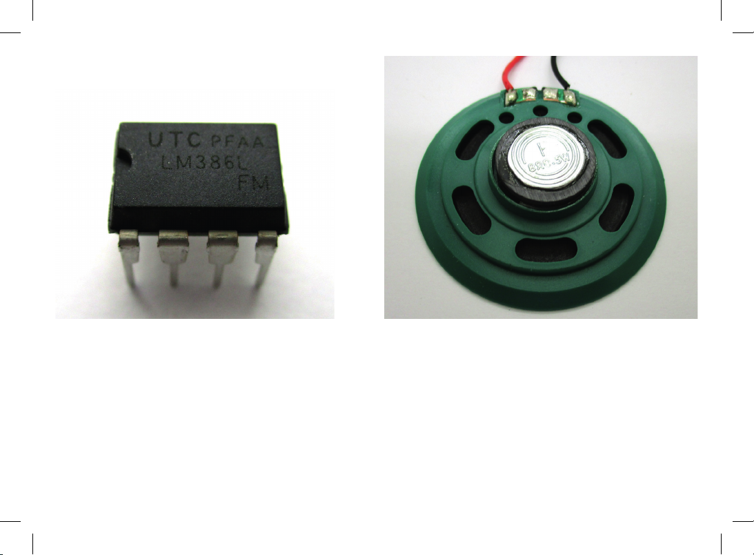
LoudspeakerLM386 amplier
The LM386 loudspeaker amplier is an integrated circuit (IC)
in a housing with eight pins, numbered from pin 1 at the bot-
tom le corner to pin 8 at the top le corner. Pin 4 (boom
right) is the negave terminal of the power supply. The ampli-
er operates at 9 V and provides 0.5 W to the loudspeaker.
The loudspeaker exhibits a resistance of 8 Ohm and can
tolerate up to 0.5 W. The volume depends mainly on how the
loudspeaker is mounted. A pleasant sound is only achieved by
installing the loudspeaker in the housing.
7

100 µF e-cap
100 nF disc capacitor
The loudspeaker must not be
connected directly to the am-
plier but requires a capacitor.
Any capacitor consists of two
metal sheets insulated against
each other. The electrolyc
capacitor (e-cap) used here
contains aluminium sheets in a
conducve uid (electrolyte).
You have to pay aenon to
the mounng direcon as
the e-cap will be destroyed
when the polarity is reversed.
The negave terminal is the
shorter leg; it is addionally marked by a
white bar. The kit contains two idencal
e-caps with a capacitance of 100 microfa-
rad (100 µF).
There is another capacitor with only a
1000th of the capacitance of the e-cap,
i.e. 100 nanofarad (100 nF). The im-
printed number 104 means 100,000 pF
(picofarad). This component is a ceramic
disc capacitor and can be mounted in
any direcon.
8

10 kΩ and 1 kΩ resistors Tuning potenometer
The resistors in the kit are of the carbon lm type and can
be mounted in any direcon. The smallest one has a resis-
tance of 100 ohm (100 Ω), the biggest one has 220 kiloohm
(220 kΩ). The resistance values are shown by three coloured
rings. The fourth, gold ring represents a tolerance of 5%. The
kit contains four resistors in total.
100 Ω: brown, black, brown
1 kΩ: brown, black, red
10 kΩ: brown, black, orange
220 kΩ: red, red, yellow
Basically, a potenometer is a resistor; however, it contains a
third contact, which is shied by turning the axis. The poten-
ometer will be mounted in the radio housing with a washer
and a nut, and a rotary knob will be screwed to the axis. This
three-pin potenometer is intended for tuning the radio.
9

The volume potenometer contains an addional switch and
thus has ve connecng wires. By turning the axis to the far
le, the radio is turned o. As a special feature of this poten-
ometer, the resistance curve is not linear but adapted to the
human sense of hearing. Hence, the middle seng provides
signicantly more than half the total resistance.
Volume potenometer
10
Table of contents


