
Efinix Titanium Ti60 F225 User manual

Titanium Ti60 F225
Development Kit User Guide
Ti60F225-DK-UG-v1.5
March 2022
www.efinixinc.com
Copyright © 2022. All rights reserved. Efinix, the Efinix logo, the Titanium logo, Quantum, Trion, and Efinity are trademarks of Efinix, Inc. All other
trademarks and service marks are the property of their respective owners. All specifications subject to change without notice.

Titanium Ti60 F225 Development Kit User Guide
Contents
Introduction..................................................................................................................................... 4
What's in the Box?.................................................................................................................................... 4
Register Your Kit........................................................................................................................................4
Download the Efinity® Software.............................................................................................................. 5
Install the USB Driver (Linux)................................................................................................................... 5
Install USB Drivers (Windows)................................................................................................................. 5
Board Functional Description..........................................................................................................7
Features.......................................................................................................................................................7
Overview..................................................................................................................................................... 8
Power On..................................................................................................................................................10
Reset..........................................................................................................................................................10
Clock Sources.......................................................................................................................................... 11
Configuration........................................................................................................................................... 11
Headers.....................................................................................................................................................12
Headers P1, P2, and P3 (Multi-Purpose).................................................................................. 13
Header J1 (USB 3.0)....................................................................................................................15
Header J2 (Power Supply)..........................................................................................................15
Header J3 (VCC Selector).......................................................................................................... 16
Header J4 (VCCAUX Selector).................................................................................................. 16
Headers J5, J6, and J7 (TR, TL, and BR Voltage)....................................................................16
Headers J8, J9, J10, and J11 (3A, 3B, 4A, and 4B Voltage)................................................. 16
Header J12 (USB FTDI FT4232)................................................................................................ 16
Header J13 (SPI Flash Voltage Leveler)................................................................................... 17
Headers J14, J15, and J16 (USB 3.0 Boot Option)................................................................ 17
Header J18 (Supply Test Points)................................................................................................17
Test Points TP1, TP2, TP3, TP4 (Ground)..................................................................................17
SD1 (Micro-SD Card Slot)...........................................................................................................17
User Outputs............................................................................................................................................18
User Inputs............................................................................................................................................... 19
USB 3.0 Controller.................................................................................................................................. 20
Setting-up USB 3.0 Boot Option for Programming................................................................ 20
Program the USB 3.0 Controller................................................................................................20
MIPI and LVDS Expansion Daughter Card.................................................................................... 21
Features.....................................................................................................................................................21
Headers.....................................................................................................................................................21
Dual Raspberry Pi Camera Connector Daughter Card..................................................................24
Features.....................................................................................................................................................24
Headers.....................................................................................................................................................25
Headers FPC1 and FPC2 (Raspberry Pi FPC15 Connector).................................................. 25
Header J1 (Optional Camera Signals)......................................................................................26
Header J2 (Development Board Connector).......................................................................... 27
Dual MIPI to DSI Converter Daughter Card..................................................................................28
Features.....................................................................................................................................................28
Headers.....................................................................................................................................................28
Header J1 (Development Board Connector).......................................................................... 29
Headers J2 and J3 (Mini-DSI Panel Connector Daughter Card)...........................................30
Mini-DSI Panel Connector Daughter Card.................................................................................... 32
Features.....................................................................................................................................................32
www.efinixinc.com

Titanium Ti60 F225 Development Kit User Guide
Headers.....................................................................................................................................................33
Headers J2 (Mini-DSI Panel Connector Daughter Card)........................................................33
Headers J4 (Test Points)............................................................................................................. 34
Header J5 (Mini-DSI Display Panel).......................................................................................... 34
Setting up the Board.....................................................................................................................35
Installing Standoffs..................................................................................................................................35
Attaching the MIPI and LVDS Expansion Daughter Card..................................................................35
Attaching the Dual Raspberry Pi Camera Connector Daughter Card..............................................36
Attaching the Display and Daughter Cards........................................................................................ 37
Mini-DSI Panel Backlight Setup................................................................................................. 38
Titanium Ti60 F225 Development Board Example Design.......................................................... 39
Set Up the Hardware..............................................................................................................................40
Running the Example Design................................................................................................................42
Mini-DSI Panel.............................................................................................................................. 42
USB UVC....................................................................................................................................... 42
Read SD Card Information......................................................................................................... 43
Creating Your Own Design........................................................................................................... 43
Restoring the Demonstration Design........................................................................................... 44
Program the Development Board........................................................................................................ 44
Sapphire RISC-V SoC Application Binary............................................................................................ 45
Copy a User Binary to Flash (Efinity Programmer)..................................................................45
Copy a User Binary to Flash (2 Terminals)...............................................................................45
Revision History.............................................................................................................................47
www.efinixinc.com

Titanium Ti60 F225 Development Kit User Guide
Introduction
Thank you for choosing the Titanium Ti60 F225 Development Kit (part number:
Ti60F225-DK), which allows you to explore the features of the Ti60 FPGA.
Whether you are capturing video, aggregating sensor data, or designing for mobile or IoT
applications, the Titanium Ti60 F225 Development Kit provides everything you need to get
started quickly. Capture video with the included Raspberry Pi camera module, process it in
the Ti60 FPGA, and then stream the result to the provided mini-DSI display. The camera
and DSI converter daughter cards support up to 2 cameras or displays, respectively. The kit
also includes an I/O expansion daughter card so you can connect to other components more
easily.
Warning: The board can be damaged without proper anti-static handling.
What's in the Box?
The Titanium Ti60 F225 Development Kit includes:
•Titanium Ti60 F225 Development Board
•1 Mini-DSI Panel Connector Daughter Card
•1 Dual MIPI to DSI Converter Daughter Card
•1 MIPI and LVDS Expansion Daughter Card
•1 Dual Raspberry Pi Camera Connector Daughter Card
•1 Mini-DSI panel
•1 Raspberry Pi v2 camera module
•1 15-pin flat cable
•1 30-pin flat cable
•2 USB type-C cable
•18 jumpers
•10 standoffs, 10 screws, and 6 nuts
•Universal AC to DC power adapter
Register Your Kit
When you purchase an Efinix development kit, you also receive a license for the Efinity®
software plus one year of software upgrades and patches. The Efinity® software is available
for download from the Support Center on the Efinix web site.
To get access to our Support Center to download your software, register your development
kit at https://www.efinixinc.com/register.
www.efinixinc.com 4

Titanium Ti60 F225 Development Kit User Guide
Download the Efinity® Software
To develop your own designs for the Ti60 device on the board, you must install the Efinity®
software. You can obtain the software from the Efinix Support Center under Efinity
Software (www.efinixinc.com/support/).
The Efinity® software includes tools to program the device on the board. Refer to the
Efinity® Software User Guide for information about how to program the device.
Learn more: Efinity® documentation is installed with the software (see Help > Documentation) and is also
available in the Support Center under Documentation (www.efinixinc.com/support/).
Install the USB Driver (Linux)
The following instructions explain how to install a USB driver for Linux operating systems.
1. Disconnect your board from your computer.
2. In a terminal, use these commands:
> sudo <installation directory>/bin/install_usb_driver.sh
> sudo udevadm control --reload-rules
Note: If your board was connected to your computer before you executed these
commands, you need to disconnect and re-connect it.
Install USB Drivers (Windows)
The Titanium Ti60 F225 Development Board development board has an FTDI FT4232H
chip to communicate with the USB port. This chip has separate channels that the board uses
for the JTAG and UART interfaces. You need to install a driver for each interface, and then
each interface appears as a unique FTDI device.
Note: If you install a composite driver, all of the interfaces appear as a composite device and you cannot
use them separately (which means you cannot use all of the features of the board).
Driver Options
The Zadig software includes a variety of drivers. When programming Efinix FPGAs, use one
of these drivers:
•libusb-win32 (version)—This driver is more stable for unplug/plug events. This driver
does not work when debugging with OpenOCD.
•libusbK (version)—Use this driver if you plan to use OpenOCD to debug any Efinix
RISC-V SoC.
Warning: Do not choose the WinUSB driver.
www.efinixinc.com 5

Titanium Ti60 F225 Development Kit User Guide
Install Drivers
To install the interface drivers in Windows:
1. Connect the FTDI USB (J12) on the board to your computer with a USB type-C cable.
2. Download the Zadig software from zadig.akeo.ie. (You do not need to install it; simply
run the downloaded executable.)
3. Run the Zadig software.
Note: To ensure that the USB driver is persistent across user sessions, run the
Zadig software as administrator.
4. Choose Options > List All Devices.
5. Repeat the following steps for each interface. The interface names end with (Interface N),
where N is the channel number.
•Select libusb-win32 or libusbK in the Driver drop-down list. (Do not choose
WinUSB.)
•Click Replace Driver.
6. Close the Zadig software.
Important: Install drivers for interfaces 0 and 1 only. You do not need to install drivers for interfaces 2
and 3 because when you connect the Titanium Ti60 F225 Development Board to your computer, Windows
automatically installs a driver for them.
www.efinixinc.com 6

Titanium Ti60 F225 Development Kit User Guide
Board Functional Description
The Titanium Ti60 F225 Development Board contains a variety of components to help you
build designs for the Titanium Ti60 device.
Figure 1: Titanium Ti60 F225 Development Board Block Diagram
4 User Pushbuttons
2 RGB LEDs
USB Type-C
Connector
USB Type-C
Connector
NOR
Flash
FTDI
FT4232
USB 3.0
Controller
MIPI RX/TX, LVDS, GPIO
Header
MIPI RX/TX, LVDS, GPIO
Header
MIPI RX/TX, LVDS, GPIO
Header
8 Data, 2 Clock,
6 GPIOs
8 Data, 2 Clock,
6 GPIOs
8 Data, 2 Clock,
6 GPIOs
25 MHz, 33.3333 MHz, 74.25 MHz
Oscillators
2 User DIP Switches
HyperRAM X16,
256 Mbit
Ti60 FPGA
Micro SD Card Slot
Features
•Efinix Ti60F225C4 device in an 225-ball FineLine BGA package
•HyperRAM x16 bits memory:
—256 Mb
—1.8 V power supply
—200 MHz maximum clock rate
—Up to 400 Mbps double-data rate
—Supports single ended clock (CK) and differential clock (CK/CK#)
•128 Mbit SPI NOR flash memory
•Three MIPI, LVDS, and GPIO high-speed connectors to attach the daughter cards
included in the kit or your own custom daughter cards
•Micro-SD card slot
•USB v3.0 interface and type-C connector
•USB Type-C connector for programming the flash or Ti60 FPGA using the Efinity®
software
•25, 33.3333, and 74.25 MHz oscillators for Ti60F225C4 PLL input
•User LEDs and switches:
—2 RGB LEDs on Ti60F225C4 banks 3B
—4 pushbutton switches (connected to bank 3B, TL and BR I/O pins)
—2 DIP switches (connected to bank 1B I/O pins)
•Power:
—12.0 V power supply connector
www.efinixinc.com 7
Titanium Ti60 F225 Development Kit User Guide
—On-board regulator sources: 0.95 V (5A), 1.2 V (5A), 1.5 V (0.5A), 1.8 V (5A),
3.3 V (5A)
—Fixed 1.8 V VCCIO for I/O banks 1A, 1B, 2A, and 2B
—Fixed 3.3 V VCCIO for I/O bank BL
—User selectable voltages from 1.8 V and 3.3 V for I/O banks TR, TL, and BR
—User selectable voltages from 1.2 V, 1.5 V, and 1.8 V I/O banks 3A, 3B, 4A, and 4B
•Power good and Ti60F225C4 configuration done LEDs
Overview
The board features the Efinix Ti60 programmable device in a 225-ball FBGA package, which
is fabricated using Efinix Quantum™ technology. The Quantum™-accelerated programmable
logic and routing fabric is wrapped with an I/O interface in a small footprint package. Ti60
devices also include embedded memory blocks and DSP blocks. You create designs for the
Ti60 device in the Efinity® software, and then download the resulting configuration bitstream
to the board using the USB connection.
Learn more: For more information on Ti60 FPGAs, refer to the Ti60 Data Sheet.
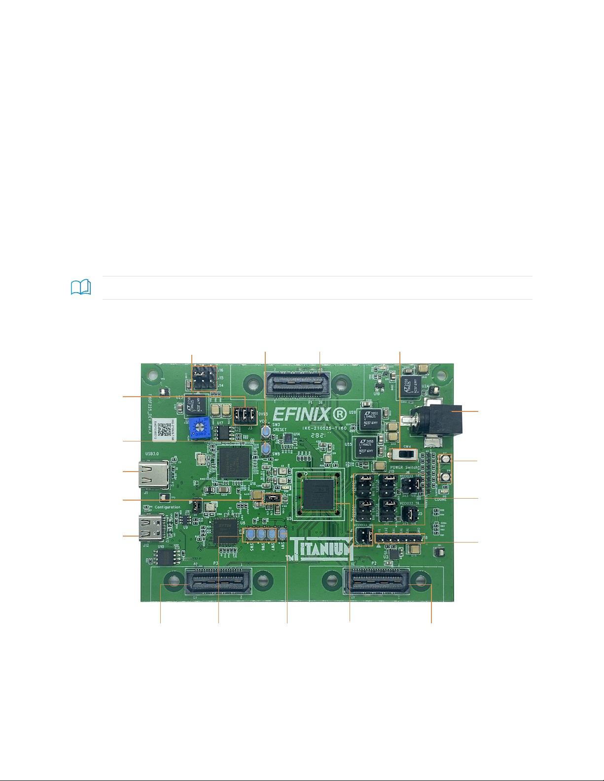
Figure 2: Titanium Ti60 F225 Development Board Components (Top)
Multi-Purpose
Connector
Multi-Purpose
Connector
Multi-Purpose
Connector
USB 3.0
Boot Options
USB Type-C
(USB 3.0)
USB Type-C
(FT4232)
User
Pushbuttons
Power Supply
Select
12 V Power
Supply
On/Off
Switch
FT4232 Reset/
User Pushbutton
USB 3.0 Reset
VCC Selector
VCCAUX
Selector
Ti60
Reset
Ti60 F225
RGB LEDs
Power Supply
Test Points
www.efinixinc.com 8

Titanium Ti60 F225 Development Kit User Guide
Figure 3: Titanium Ti60 F225 Development Board Components (Bottom)
Micro-SD
Card Slot
Dipswitches
Figure 4: Titanium Ti60 F225 Development Board Header and LED Definition
Ti60
J16
J15
J14
J3
1
1
1
2
2
2
3
3
3
2
1 2 3 4 5 6
1
2
3
4
5
6
1
2
3
4
5
6
1
2
3
4
5
6
1
2
3
4
5
6
1
2
3
4
5
6
2
1
4
3
2
1
4
3
2
1
4
3
J4
J13
USB
3.0
Power
Input
USB
FT4232 J5
J6
D15
(CDONE)
D16
D17
J7
J8
J9
J10
J11
J18
D22
(Power Good)
D20
(NSTATUS)
1
2
www.efinixinc.com 9

Titanium Ti60 F225 Development Kit User Guide
The Titanium Ti60 F225 Development Board provides three multi-purpose 0.8 mm high-
speed ground plane sockets. These sockets can be used for GPIO, MIPI CSI-2 TX/RX, and
LVDS TX/RX. The board includes two USB type-C ports, one for USB 3.0 interface and the
other for the FTDI interface.
The FTDI FT4232H module has four channels to support the following interfaces:
•SPI—FTDI interface 0
•FPGA JTAG—FTDI interface 1
•FPGA UART—FTDI interface 2
•USB 3.0 chip UART—FTDI interface 3
The FTDI module receives the Ti60 configuration bitstream from a USB host and writes to
the Ti60 FPGA in SPI passive configuration. You can write a configuration bitstream to the
on-board SPI NOR flash memory through JTAG with the JTAG SPI Flash Loader Core.
Additionally, it supports a UART interface to the Ti60 and the USB 3.0 chip.
The SPI NOR flash memory stores the configuration bitstream. The Ti60 device accesses this
configuration bitstream when it is in active configuration mode (default).
Learn more: Refer to the Titanium Ti60 F225 Development Board Schematics and BOM for more
information about the components used in the Titanium Ti60 F225 Development Board.
Power On
To turn on the development board, turn on switch SW4. The 12 V DC power is input to
the on-board regulators to generate the required 3.3 V, 2.5 V, 1.8 V, 1.5 V, and 1.2 V for
components on the board. When these voltages are up and stable, the power-good LED, D22
illuminates, giving you a visual confirmation of the status.
Reset
The Ti60F225C4 device is typically brought out of reset with the CRESET signal. Upon
power up, the Ti60F225C4 device is held in reset until CRESET toggles high-low-high.
Note: You can manually assert the high-low-high transition with pushbutton switch SW3.
CRESET has a pull-up resistor. When you press SW3, the board drives CRESET low; when
you release SW3, the board drives CRESET high. Thus, a single press of SW3 provides the
required high-low-high transition.
After toggling CRESET, the Ti60F225C4 device goes into configuration mode and reads
the device configuration bitstream from the flash memory. When configuration completes
successfully, the device drives the CDONE signal high. CDONE is connected to a green LED
(D15), which turns on when the Ti60F225C4 device enters user mode.
www.efinixinc.com 10
Table of contents
Other Efinix Microcontroller manuals


Popular Microcontroller manuals by other brands

AMS
AMS AS7261 Demo Kit user guide

Novatek
Novatek NT6861 manual

Espressif Systems
Espressif Systems ESP8266 SDK AT Instruction Set

Nuvoton
Nuvoton ISD61S00 ChipCorder Design guide

STMicrolectronics
STMicrolectronics ST7 Assembler Linker user manual

Texas Instruments
Texas Instruments Chipcon CC2420DK user manual





Texas Instruments
Texas Instruments TMS320F2837 D Series Workshop Guide and Lab Manual

CYPRES
CYPRES CY14NVSRAMKIT-001 user guide

Texas Instruments
Texas Instruments INA-DUAL-2AMP-EVM user guide

Espressif Systems
Espressif Systems ESP8266EX Programming guide

Abov
Abov AC33M8128L user manual

Laird
Laird BL654PA user guide