East Tester ET3325 User manual
ET3325 Function/ Arbitrary Waveform Generator
User Manual
HANGZHOU ZHONGCHUANG ELECTRON CO., LTD

1
Contents
Introduction to ET3325 Function/ Arbitrary Waveform Generator.................................................3
Key Features........................................................................................................................................3
Product Model..................................................................................................................................... 3
1. Quick Start.......................................................................................................................................4
1.1 Introduction to Front and Rear Panels.................................................................................. 4
1.2 Introduction to Interface........................................................................................................4
1.3 Waveform Setup.................................................................................................................... 5
1.4 Output Setup..........................................................................................................................7
1.5 Modulation/Frequency Sweep/Burst Output Setup.............................................................. 7
1.6 Introduction to Digital Input................................................................................................. 8
1.7 Introduction to Functions of Frequency Meter/System Setup/Help.....................................9
2. Advanced Operation Instructions....................................................................................................9
2.1 Basic Waveform Setup........................................................................................................ 10
2.1.1 Sine wave setup........................................................................................................10
2.1.2 Square wave setup....................................................................................................13
2.1.3 Set ramp wave.......................................................................................................... 15
2.1.4 Set pulse wave..........................................................................................................17
2.1.5 Set noise wave..........................................................................................................19
2.1.6 Set arbitrary wave.................................................................................................... 20
2.2 Modulation Waveform Setup.............................................................................................. 28
2.2.1 Amplitude Modulation (AM)................................................................................... 28
2.2.2 Frequency Modulation (FM)....................................................................................30
2.2.3 Phase Modulation (PM)........................................................................................... 31
2.2.4 Amplitude Shift Keying (ASK)............................................................................... 33
2.2.5 Frequency Shift Keying (FSK)................................................................................ 34
2.2.6 Phase Shift Keying (PSK)........................................................................................35
2.3 Frequency Sweep Waveform Setup.................................................................................... 37
2.4 Burst Waveform Setup........................................................................................................ 39
2.5 Sync Output (CH1)..............................................................................................................42
2.6 Frequency Meter................................................................................................................. 43
2.7 Assist System Function Setup............................................................................................. 44
2.7.1 Channel 1/2 output parameter setup........................................................................ 44
2.7.2 System setup.............................................................................................................45
2.7.3 File storage............................................................................................................... 46
2.7.4 Interface....................................................................................................................50
2.7.5 Calibration................................................................................................................50
2.7.6 System upgrade........................................................................................................ 50
2.7.7 System information.................................................................................................. 51
2.8 Help..................................................................................................................................... 51
2.9 Telecommunication............................................................................................................. 52
2.9.1 Establishment of communication between instrument and the PC......................... 52
3. Technical Specifications................................................................................................................53

2
3.1 Product Technical Indicators...............................................................................................53
3.2 General Technical Specifications........................................................................................ 59
4.Appendices................................................................................................................................59
Appendix A: Accessories.......................................................................................................... 59
Appendix B: Maintenance and Cleaning.................................................................................. 60

3
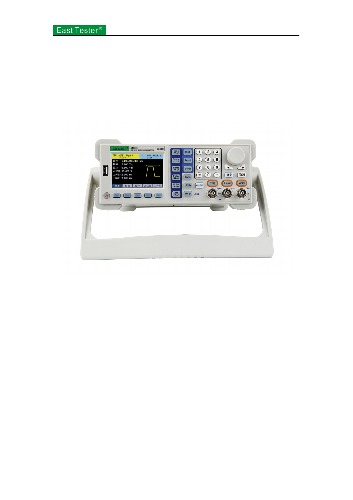
Introduction to ET3325 Function/ Arbitrary Waveform
Generator
ET3325 function/arbitrary waveform generator is equipped with direct digital synthesis (DDS)
technology which enables output signal to be stable and accurate.
Instrument output channel sets CH1 channel output and CH2 channel output. CH1 channel is
major output channel for output of all the following functions; CH2 channel is an auxiliary
channel for output of basic waveform and arbitrary wave.
Key Features
3.5-inch 480×320TFT LCD with clear graphic interface
Chinese / English menu available
Press key for help and information
File management supporting USB flash disk and local storage
ET3325 output with the highest output frequency is ET3310 Model is 10MHz, ET3325
Model is 25MHz,ET3340 Model is 40MHz, ET3360 Model is 60MHz and ET 3370
Model is 70MHz.
Sampling rate: 160MSa/S, vertical resolution: 12 bit and storage depth: 16k
5 basic waveforms and 32 arbitrary waveforms in-built
Pulse wave output set in edge time
Internal/external AM, FM, PM, ASK, FSK and PSK modulation function
Output of linear/logarithmic frequency sweep and burst waveform
Frequency meter of high precision of 200MHz
With RS232 interface, USB Device, USB Host interface supporting USB flash disk
storage
Multi-functional arbitrary waveform editing software equipped
Product Model
has ET3360 models, namelyET3310, ET3325, ET3340, ET3360 and ET3370. The manual takes
ET3340 as an example, in which specifications have covered all the functions and performances of
ET3325.
4
1. Quick Start
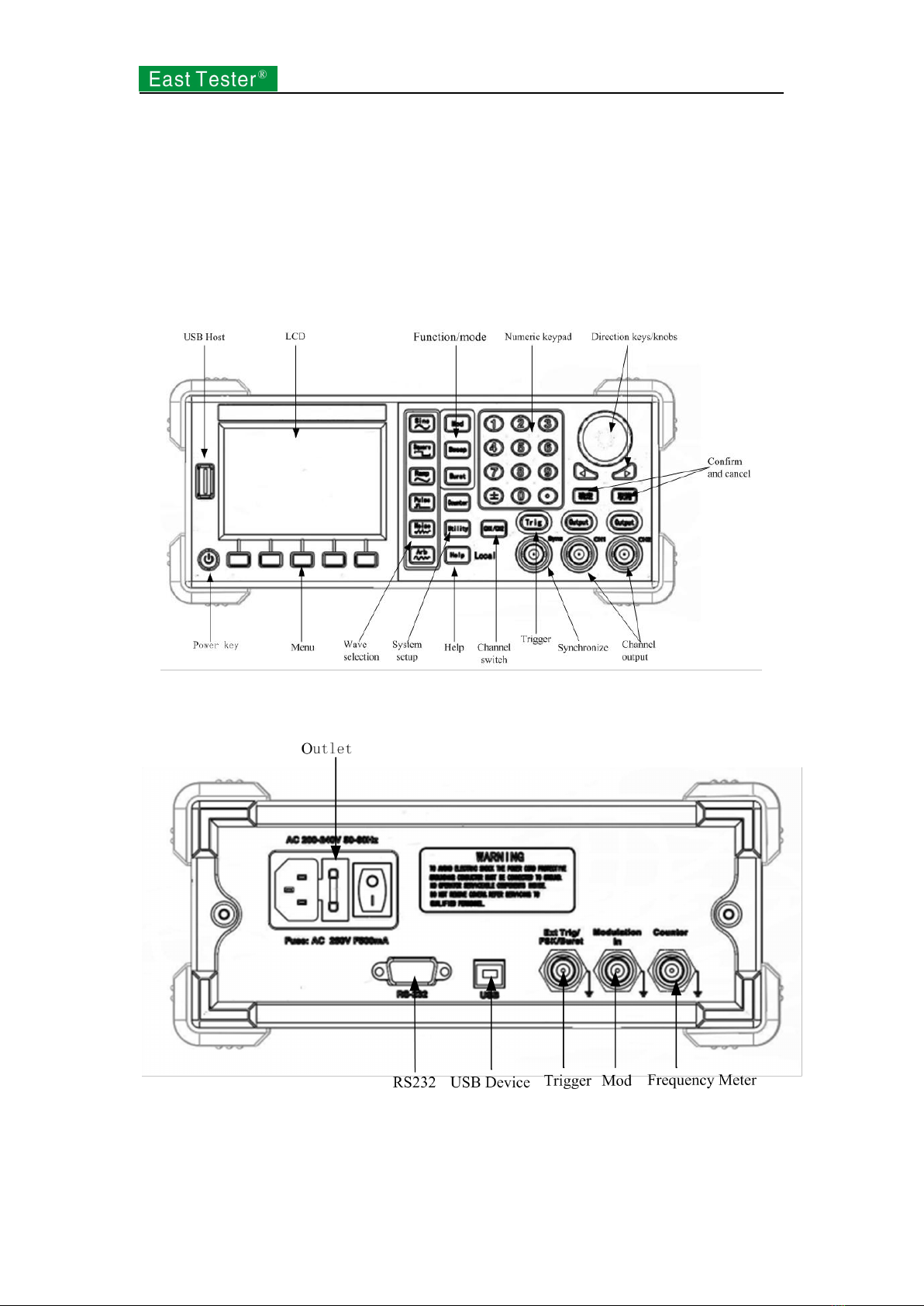
1.1 Introduction to Front and Rear Panels
This section describes front and rear panels of for your quick understanding of function and
usage.
Front panel includes liquid crystal, keys and output terminal and so on. Keys include:
Function/mode, reusable keys, numeric keys and direction keys/knobs.
Figure 1-1 Front panel
The rear panel consists of input terminal, communication interface and power interface.
Figure 1-2 Rear Panel
1.2 Introduction to Interface
5
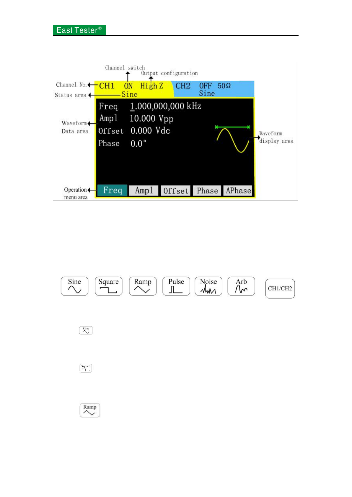
Basic operation interface is shown in Figure 1-3.
Figure 1-3 Interface
1.3 Waveform Setup
There is a series of keys with waveform displaying on the right of the operation panel, which are
sine wave, square wave, ramp wave, pulse wave, noise wave and arbitrary wave. There is a
common key as well: switch of CH1/CH2 channels.
The following routine will guide you gradually familiar with the setup of these keys.
Waveform keys Channel switch
Figure 1-4 Key Selection
1. Press , waveform display area will turn to sine signal and show Sine in the status area.
Sine waves of different parameter values are accessible through the setup of frequency/cycle,
amplitude/high-level, offset/low-level and phase.
2. Press , waveform display area will turn to square signal and show Square in the status
area. Square waves of different parameter values are accessible through the setup of
frequency/cycle, amplitude/high level, offset/low level, duty cycle and phase.
3. Press , waveform display area will turn to ramp signal and show Ramp in the status
area. Ramp waves of different parameter values are accessible through the setup of
frequency/cycle, amplitude/high-level, offset/low-level, symmetry and phase.
6
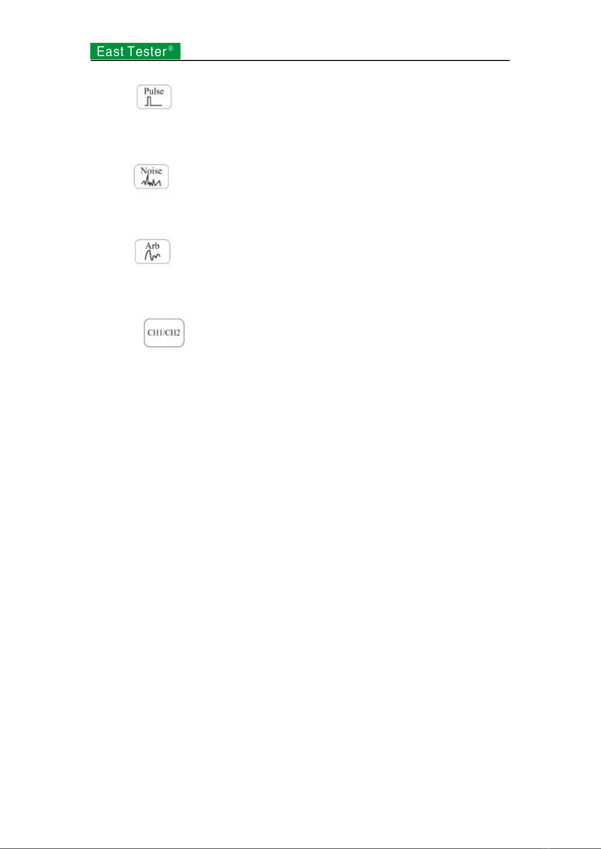
4. Press , waveform display area will turn to pulse signal and show Pulse in the status
area. Pulse waves of different parameter values are accessible through the setup of frequency/cycle,
amplitude/high-level, offset/low-level, symmetry and rising/trailing edge.
5. Press , waveform display area will turn to noise signal and show Noise in the status
area. Noise waves of different parameter values are accessible through the setup of amplitude/high
level and offset/low level.
6. Press , waveform display area will turn to arbitrary signal and show Arb in the status
area. Arbitrary waves of different parameter values are accessible through the setup of
frequency/cycle, amplitude/high-level, offset/low-level and phase.
7. Press to switch channels. The selected channel is for parameter setup.
Background color of liquid crystal changes in compliance with the switch of channels.
7
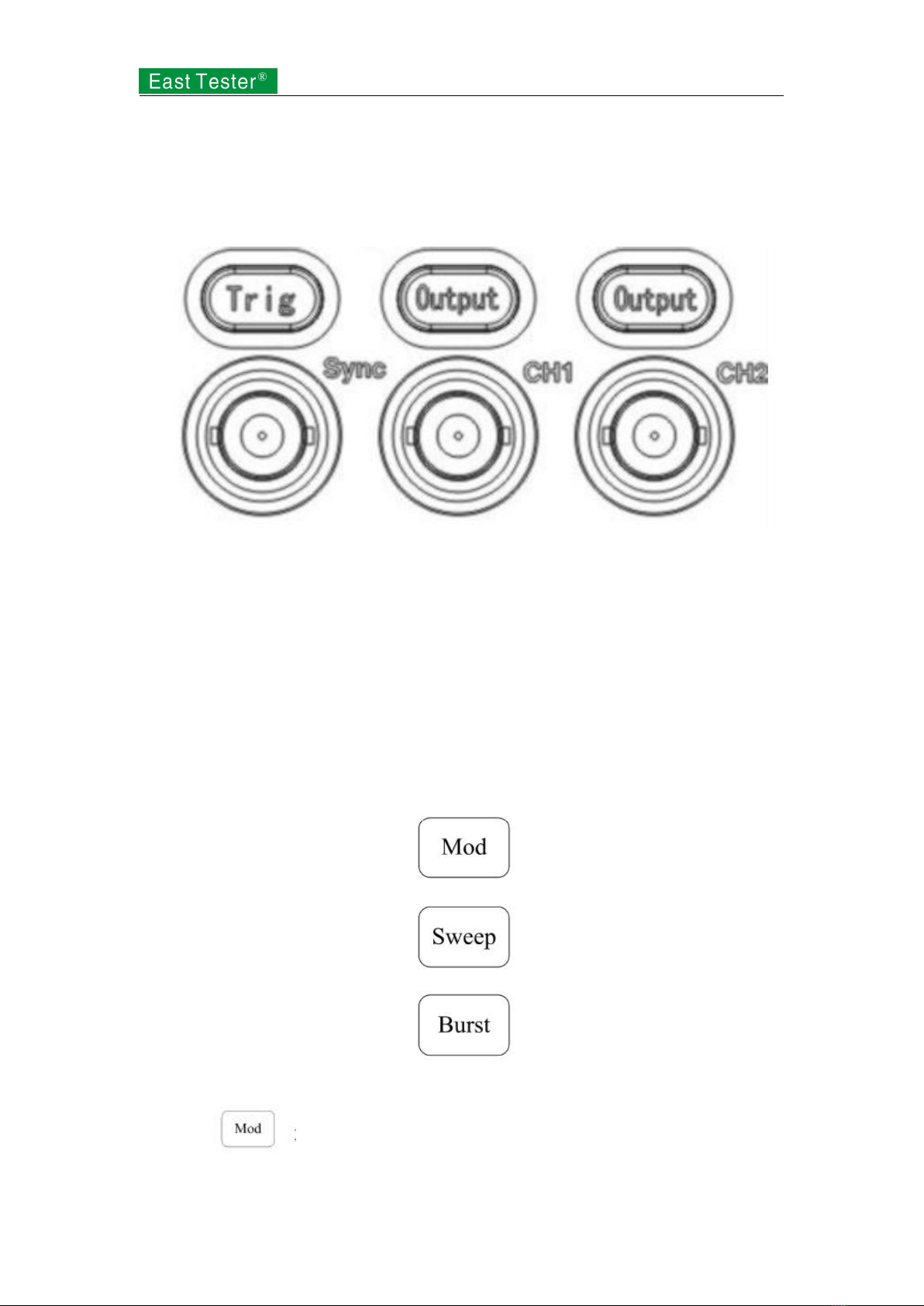
1.4 Output Setup
As shown in Figure 1-5, there are ET3325 Output keys at the bottom right of the front panel for
channel output control andET3310 Trig key for trigger output. The following examples will offer
you guidance on these functions.
Figure 1-5 Channel Output
1. Press Output to start or forbid output signal of output connector in the front panel. The
channel pressed Output displays ON and is lit.
2. When sweep and burst output, if Channel 1 is in output status and trigger is manual, trigger
outputs signal for once if pressing the trigger key. For non-manual trigger, manual trigger
would realized by pressing the trigger key.
1.5 Modulation/Frequency Sweep/Burst Output Setup
ET3340 keys on the right side of waveform are for the output of modulation, frequency sweep and
burst respectively, which function is for Channel 1 only. The following specifications will offer
you guidance on the setup of these functions.
Figure 1-6 Keys of Modulation/Frequency Sweep/Burst
1. Press to output modulated waveform. Change output waveform through the
change in parameters such as type, internal modulation/external modulation, depth, frequency and
8
modulated wave.
Modulation types include AM, FM, PM, ASK, FSK and PSK. Modulating signals include sine
wave, square wave, ramp wave, up-ramp and down-ramp.
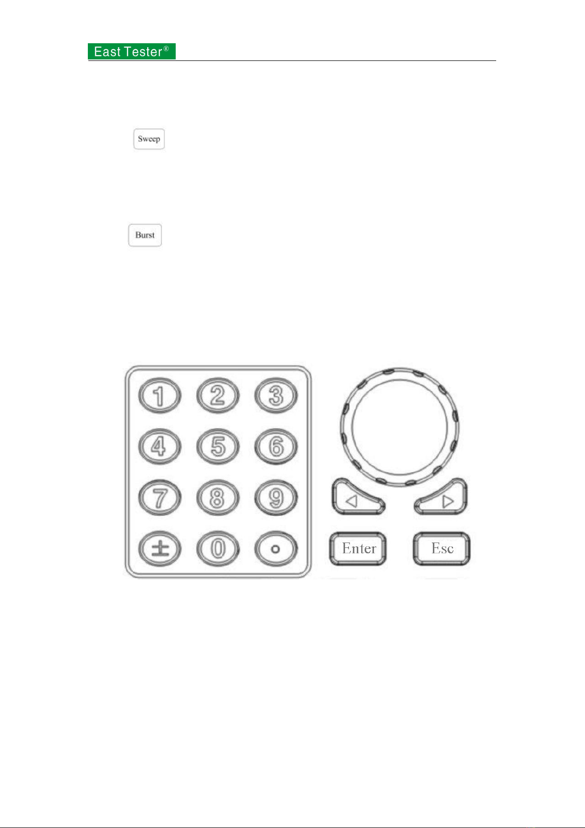
2. Press to conduct frequency sweep on sine wave, square wave, ramp wave, pulse
wave or arbitrary waveform.
In the frequency sweep mode, the frequency of output waveform is in constant change from the
start frequency to the stop frequency at a sweep rate.
3. Press and it will generate burst waveform of sine wave, square wave, ramp wave,
pulse wave or arbitrary waveform.
1.6 Introduction to Digital Input
As shown in Figure 1-7, ET3325 sets of keys are on the front panel, which are numeric keypad,
left-right direction keys and knobs and confirmation/cancellation key. The following specifications
will offer you guidance on the use of digital input.
Figure 1-7 Numeric keypads, direction keys and knobs and confirmation/cancellation key
Direction keys
Switch of digits and system setup interface for menu selection. The left key is applicable to
backspace under numeric keypad input.
Knobs
Digit Alternation. Make a clockwise rotation to plus 1 and an anticlockwise ONE/10MHZ to
minus 1 if the change is within the range of 0~9.
Switch of internal waveform type, system setup interface for selection of menu and characters
input of file name.
Numeric keypad
Input the desired value directly and alter the size of parameters.
9
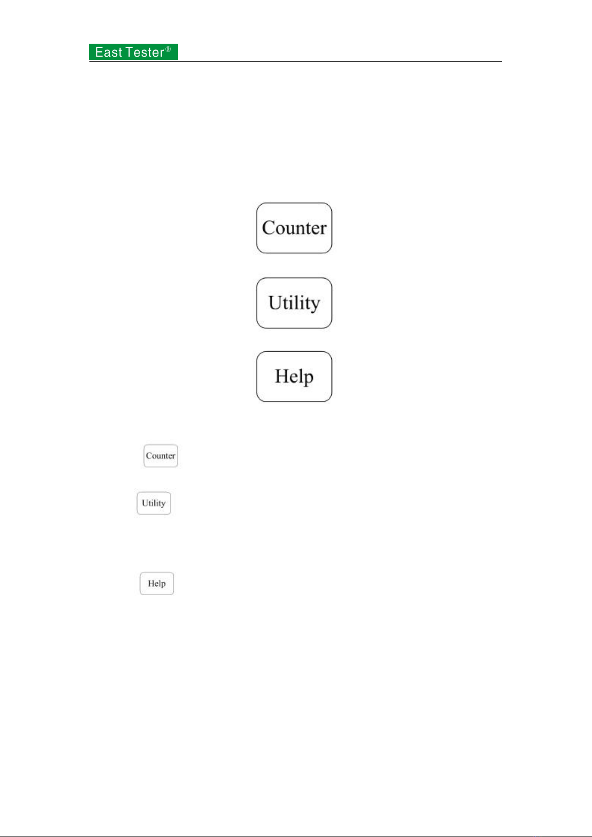
1.7 Introduction to Functions of Frequency Meter/System
Setup/Help
As shown in Figure 1-8, ET3340 keys are below keys of modulation/frequency sweep/burst on
the front panel to set frequency meter, system setup and help respectively. The following
specifications will offer you guidance on the setup of these functions.
Figure 1-8 Keys of Frequency Meter/System Setup/Help
1. Press to check the current measured value of the frequency meter.
2. Press to set output parameters of Channel 1 and 2, buzzer switch, language switch,
file storage, interface information and system information; execute instrument calibration and
system update.
3. Press to check assistance information list.
2. Advanced Operation Instructions
You have acquired preliminary knowledge on the functions of keys and knobs of all functional
areas on the front panel of ET3340 and are able to make basic operation on function/arbitrary
waveform generator through previous introduction.
This section is introduction to basic waveform setup, arbitrary waveform setup, modulating
waveform setup, frequency sweep waveform setup, burst waveform output, and use of frequency
meter, system function setup and assistance in use.
Table of contents
Other East Tester Test Equipment manuals

East Tester
East Tester ET-AY30 User manual

East Tester
East Tester ET44 Series User manual

East Tester
East Tester ET1300 User manual

East Tester
East Tester ET5410 User manual

East Tester
East Tester ET5420 User manual

East Tester
East Tester ET-2715 User manual

East Tester
East Tester ET-2712 RTD User manual

East Tester
East Tester ET5300 User manual

East Tester
East Tester ET2725A User manual


