East Tester ET-2715 User manual
ET-2715 Current and Voltage Calibrator
ET-1715 Current and Voltage Calibrator
Users Manual
Hangzhou Zhongchuang Electron Co., Ltd.

Contents
1 Basic Introduction........................................................................................................... 1
1.1 Function............................................................................................................... 1
1.2 Summary of Source and Measure Functions....................................................... 1
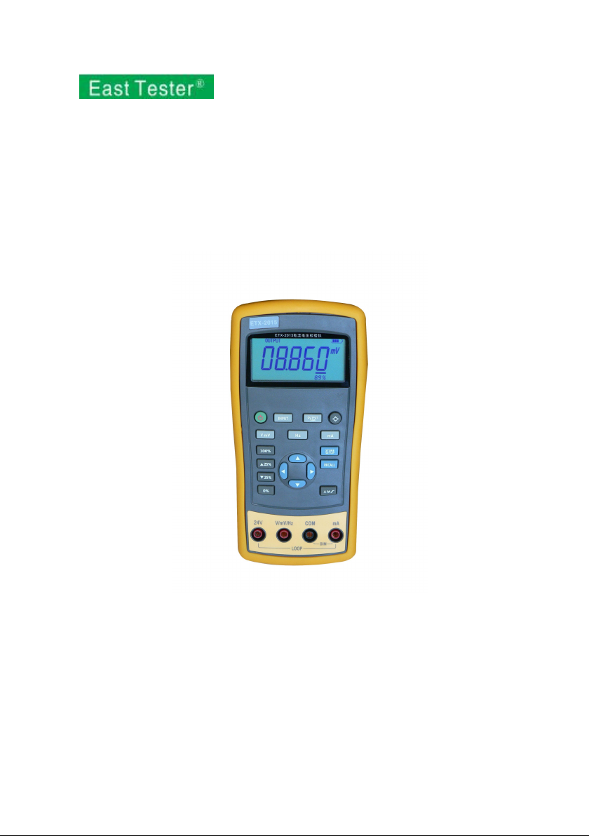
1.3 Interface (terminal) Description...........................................................................2
1.4 Key Description................................................................................................... 3
1.5 Display Screen..................................................................................................... 4
2 Basic Operation...............................................................................................................5
2.1 Measure and Source............................................................................................. 5
2.2 Shut Down Mode................................................................................................. 7
2.3 Backlight Brightness Adjustment.........................................................................8
3 Function Usage............................................................................................................... 9
3.1 DC V and DC mV Measurement......................................................................... 9
3.2 DC mA measurement.........................................................................................10
3.3 Current Measurement with Loop Power............................................................10
3.4 Frequency measurement.....................................................................................11
3.5 DC V Source...................................................................................................... 12
3.6 DC mV Source................................................................................................... 12
3.7 DC mA Source (active)................................................................................12
3.8 Simulating a 4- to 20-mA Transmitter............................................................... 13
3.9 Frequency Output...............................................................................................14
4 Advanced Application................................................................................................... 15
4.1 Setting 0 % and 100 % output parameters......................................................... 15
4.2 Automatic Ramp the Output.............................................................................. 16
4.3 Factory Reset......................................................................................................16
5 Power............................................................................................................................ 17
5.1 Charge................................................................................................................ 17
6 Specifications................................................................................................................ 18
6.1 DC Voltage Measurement..................................................................................18
6.2 DC voltage Source............................................................................................. 18

6.3 DC mA Measurement........................................................................................ 19
6.4 DC mA Source................................................................................................... 19
6.5 Frequency Measurement.................................................................................... 19
6.6 Frequency Source...............................................................................................20
7 Product Accessories...................................................................................................... 21
7.1 Standard Accessories......................................................................................... 21
7.2 Optional accessories...........................................................................................21
8 Warning......................................................................................................................... 22

1
1 Basic Introduction
1.1 Function
Source of voltage, current and frequency.
Measure of voltage, current, loop current and frequency.
Manual stepping and automatic stepping and ramping.
Support for PC communication
1.2 Summary of Source and Measure
Functions
Function
Measure
Source
DC V
0~30 V
0~10 V
DC mV
0~100 mV
0~100 mV
DC mA
0~24 mA
0~24 mA
Frequency
1.000Hz~99.999kHz
0.00Hz~20.000kHz
Others
24V power supply, Step, Ramp.

2
1.3 Interface (terminal) Description
Figure 1.3-1
No.
Name
Description
①
Communication and
charging connector
Connect power adaptor to charge batteries or
connect the calibrator to the computer.
②
Current terminal
terminal for current measure and source.
③
COM terminal
All measure and source public terminal.
④
V, mV, Hz terminal
terminal for voltage, milli volt, frequency
measure and source.
⑤
24V terminal
24V power supply terminal, used in LOOP mode

3
1.4 Key Description
Figure 1.4-1
No.
Description
①
Turns the power on or off
②
Selects the measurement mode
③
Selects output and analog transmitter mode.
④
Enables backlight switch display during start, enters backlight
brightness control mode.
⑤
Selects current or loop function
4
⑥
Sets and saves calibrator parameters setting
⑦
Recovers factory default setting
⑧
Sets manual output
⑨
Cycles through:
slow repeating 0%-100%-0% ramp
Fast repeating 0 % - 100 % - 0 % ramp
Repeating 0 % - 100 % - 0 % ramp in 25 % steps
⑩
Set output by 0% of span, Press and hold to store the source value
as the 0 % value
⑾
Decrements output by 25% of span.
⑿
Increments output by 25% of span.
⒀
Sets output by 100% of span, Press and hold to store the source
value as the 100 % value.
⒁
Selects DC V or DC mV function
⒂
Selects frequency function
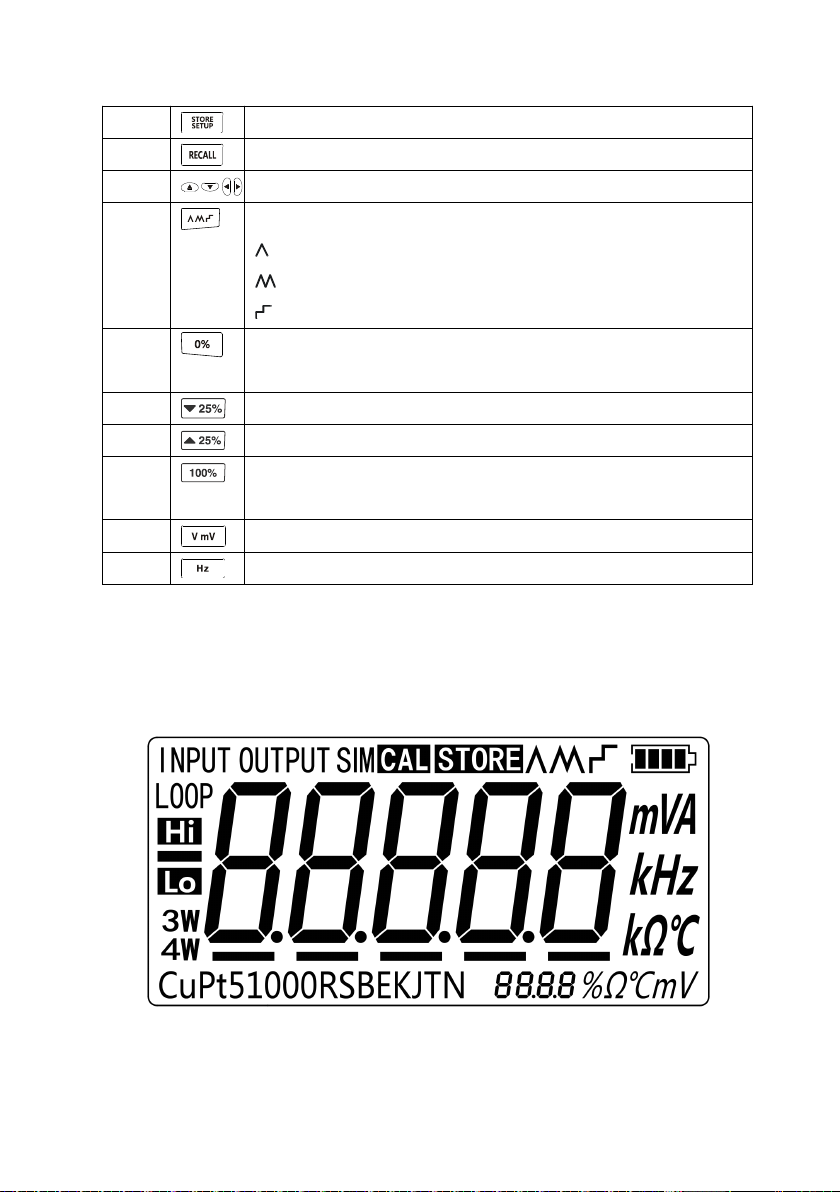
1.5 Display Screen
Figure 1.5-1

5
2 Basic Operation
2.1 Measure and Source
This section acquaints you with some basic operations of ETX-2015/ ETX-1815.
Proceed as follows:
1. The connection of the calibrator as shown in Figure 2.1-1.
Figure 2.1-1

6
2. Press more than 2 seconds to turn on the calibrator. The calibrator checks
itself, including check on internal circuit and LCD, during which, LCD displays
all contents for 1s as shown in Figure 2.1-2:
Figure 2.1-2
3. Then the product model(2015)and automatic shutdown time(30 min)will
be displayed for 2 seconds as shown in Figure 2.1-3.
Figure 2.1-3
4. Press switch to the voltage mode.
5. Press to enter into output mode selection as shown in Figure 2.1-4.
Figure 2.1-4
6. Press and to increase or decrease 1 of the horizontal line position (the
number automatic carry but the position of the line have no change); press or
to select a digit to change.

7
7. Press to select 1 V for the output value, and then press and hold
until the buzzer works to enter 1V as the 0% value.
8. Press to select 5 V for the output value, and then press and hold
until the buzzer work to enter 5V as the 100% value.
9. Press or to step between 0 and 100% in 25% step increments.
The screen will display as shown in Figure 2.1-5.
Figure 2.1-5
2.2 Shut Down Mode
The calibrator comes with the shutdown mode enabled for a time duration set to 30
minutes (displayed for about 2 seconds when the calibrator isinitially turned on). When
the shutdown mode is enabled, the calibrator will automatically shutdown after the
time duration has elapsed from the time the last key was pressed. To disable the
shutdown mode, press and simultaneously. To enable the mode, press
and simultaneously. To adjust the time duration, press and
simultaneously, the screen will display as shown in Figure 2.2-1,then press and/or
to adjust the time between 1 and 30 minutes and then press to store the
new time duration (Without pressing any key for 5 seconds, the calibrator will quit
from the adjustment automatically).
This manual suits for next models
1
Table of contents
Other East Tester Test Equipment manuals

East Tester
East Tester ET44 Series User manual

East Tester
East Tester ET1300 User manual

East Tester
East Tester ET2725A User manual

East Tester
East Tester ET-2712 RTD User manual

East Tester
East Tester ET3325 User manual

East Tester
East Tester ET5300 User manual

East Tester
East Tester ET5420 User manual

East Tester
East Tester ET-AY30 User manual

East Tester
East Tester ET5410 User manual


