Eagle EVR-150 User manual
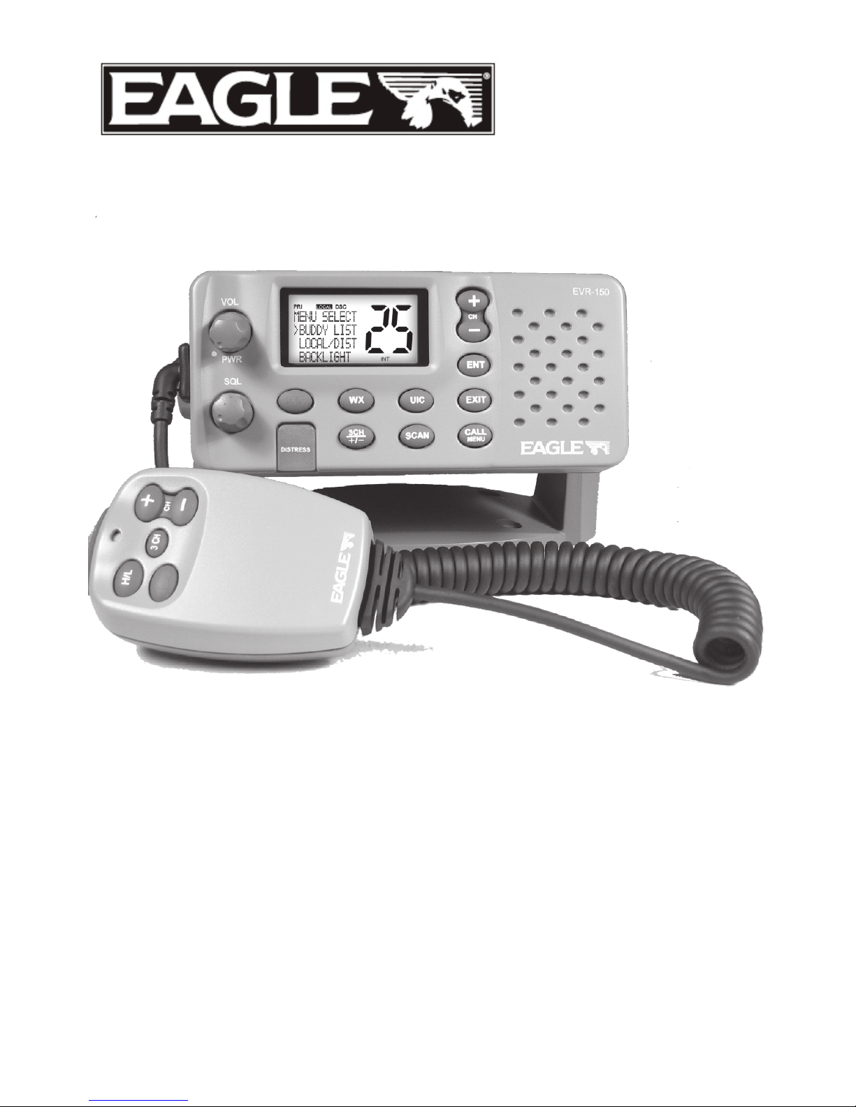
EVR-150
VHF Radio
Installation and Operation
Instructions
www.eaglesonar.com
Pub. 988-0158-041
Copyright © 2007 Navico
All rights reserved.
Eagle® is a registered trademark of Navico
No part of this manual may be copied, reproduced, republished, transmitted or
distributed for any purpose, without prior written consent of Eagle Electronics.
Any unauthorized commercial distribution of this manual is strictly
prohibited.
Eagle Electronics may find it necessary to change or end our policies,
regulations, and special offers at any time. We reserve the right to do so without
notice. All features and specifications subject to change without notice. All
screens in this manual are simulated. On the cover: EVR-150 shown. Other
models covered in the manual are similar.
For free owner’s manuals and the most current information on this product, its
operation and accessories, visit our web site: www.eaglesonar.com
Eagle Electronics
P.O. Box 669
Catoosa, OK USA 74015
Printed in China.
IMPORTANT SAFETY INFORMATION
Please read carefully before installation and use.
CAUTION
!
!
CAUTION
DANGER
WARNING
This is the safety alert symbol. It is used to alert you to potential personal
injury hazards, Obey all safety messages that follow this symbol to avoid-
possible injury or death.
CAUTION
!
!
CAUTION
DANGER
WARNING
WARNING indicates a potentially hazardous situation which, if not avoided,
could result in death or serious injury
CAUTION
!
!
CAUTION
DANGER
WARNING
CAUTION indicates a potentially hazardous situation which, if not avoided,
could result in minor or moderate injury.
CAUTION
!
!
CAUTION
DANGER
WARNING
CAUTION used without the safety alert symbol indicates a potentially haz-
ardous situation which, if not avoided, may result in property damage.

Table of Contents
Installation .........................................................................................................................5
Section 1 - General Information.......................................................................................... 13
1-1 Features ..................................................................................................................................................................13
1-2 Customizing Your Eagle VHF Radio .......................................................................................................14
1-3 How to Display and Navigate Menus...................................................................................................14
1-4 How to Enter Alphanumeric Data..........................................................................................................14
1-5 LCD Symbols and Meanings ....................................................................................................................14
1-6 Basic Operation and Key Functions ......................................................................................................16
Section 2 - The Radio Menu (MENU)..................................................................................... 19
2-1 Radio Menu Options (Menu) ...................................................................................................................19
2-2 Maintain Your Buddy List (BUDDY LIST) .............................................................................................20
2-2-1 Add an Entry ...............................................................................................................................................20
2-2-2 Edit an Entry................................................................................................................................................20
2-2-3 Delete an Entry..........................................................................................................................................21
2-3 Local or Distance Sensitivity (LOCAL/DIST)......................................................................................21
2-3-1 Set Distance Sensitivity ........................................................................................................................21
2-3-2 Set Local Sensitivity ................................................................................................................................21
2-4 Backlighting (BACKLIGHT) and Contrast (CONTRAST)..............................................................21
2-4-1 Set the Backlighting Level..................................................................................................................22
2-4-2 Set the Contrast Level...........................................................................................................................22
2-5 GPS Data and Time (GPS/DATA)...............................................................................................................22
2-5-1 Manually Enter Position and UTC Time (MANUAL) .............................................................22
2-5-2 Local Time (TIME OFFSET)..................................................................................................................23
2-5-3 Time Format Options (TIME FORMAT)........................................................................................23
2-5-4 Time Display Options (TIME DISPLAY) ........................................................................................24
2-5-5 Position Display Options (LL display)...........................................................................................24
2-5-6 Course and Speed Display Options (COG/SOG)...................................................................24
2-5-7 GPS Alert Options (ALERT) ................................................................................................................25
2-6 GPS Simulator (SIMULATOR)......................................................................................................................25
2-7 Reset to factory defaults (RESET)............................................................................................................25
Section 3 - Radio Setup Menu (RADIO SETUP) ....................................................................... 26
3-1 Radio Setup Menu (RADIO SETUP)........................................................................................................26
3-2 Channel Names (CH NAME)......................................................................................................................26
3-3 RING & BEEP Volume (RING VOLUME) & (BEEP VOLUME)........................................................27
3-4 Internal Speaker connections (INT SPEAKER)..................................................................................27
3-5 Set the Priority Channel (watch MODE) .............................................................................................27
3-6 Weather Alert (Wx ALERT) .........................................................................................................................28
3-7 NMEA protocol (COM PORT).....................................................................................................................28
Section 4 - DSC Setup Menu (DSC SETUP) ..............................................................................29
4-1 DSC Setup - Menu Options........................................................................................................................29

4-2 Enter Your User MMSI (USER MMSID)...................................................................................................29
4-3 Maintain Your Groups (GROUP SETUP) ...............................................................................................30
4-3-1 Create a Group (GROUP SETUP)......................................................................................................30
4-3-2 Edit Group Name Details ....................................................................................................................30
4-3-3 Delete a Group ..........................................................................................................................................31
4-4 Response to Individual Calls (INDIV REPLY)......................................................................................31
4-5 DSC functionality options (DSC FUNC)...............................................................................................31
4-6 Response Type to LL POLLING Calls (LL REPLY) .............................................................................32
Section 5 - Sending and Receiving DSC Calls..................................................................33
5-1 WHAT IS DSC?......................................................................................................................................................33
5-2 Sending dsc calls ..............................................................................................................................................33
5-2-1 Make a Routine Call (INDIvidual)....................................................................................................34
5-2-2 Retrying a Routine Call.........................................................................................................................34
5-2-3 Acknowledgement of an Individual Incoming Call (INDIV)..........................................34
5-2-4 Recall the Most Recent Incoming Call (LAST)........................................................................35
5-2-5 Call a Group (GROUP)............................................................................................................................35
5-2-6 Call All Ships (ALL SHIPS).....................................................................................................................35
5-2-7 Call using the Call Log (CALL LOG.................................................................................................36
5-2-8 Call using the Distress Log (DIST LOG)........................................................................................36
5-2-9 Request the LL Position of a Buddy (LL REQUEST)..............................................................37
5-3 Receiving DSC Calls.........................................................................................................................................37
5-3-1 Receiving an All Ships Call (ALL SHIPS).......................................................................................38
5-3-2 Receiving an Individual Call (INDIV).............................................................................................38
5-3-3 Receiving a Group Call (GROUP).....................................................................................................38
5-3-4 Receiving a Geographic Call (GEOGRAPH)...............................................................................39
5-3-5 Receiving a Polled Position Call (POSITION)............................................................................39
Section 6 - Distress Calls ..................................................................................................... 40
6-1 Sending a Distress Call .................................................................................................................................40
6-2 Receiving a Distress Call (DISTRESS!).....................................................................................................41
6-3 Distress Acknowledgement (distress ack) or Relay ...................................................................41
Appendix A - Technical Specifications ..................................................................................42
Appendix B - Troubleshooting............................................................................................. 44
Appendix C - VHF Marine Channel Charts .............................................................................45
C-1 international Channel Chart......................................................................................................................45
C-2 USA Channel Chart .........................................................................................................................................47
C-3 CANADA Channel Chart ..............................................................................................................................49
Appendix D - Wiring for EAGLE GPS models........................................................................... 52
Appendix E - MMSI and License Information......................................................................... 54
Eagle Warranty.................................................................................................................. 55
How to Obtain Service........................................................................................................ 56
5EAGLE - EVR-150 Installation and Operation Instructions
This Eagle radio is designed to generate a digital maritime distress call to facilitate search and
rescue. To be effective as a safety device, this radio must be used only within the geographic
range of a shore-based VHF marine Channel 70 distress and safety watch system. The
geographic range may vary but under normal conditions is approximately 20 nautical miles.
Installation
Installation Options
There are two ways to install the radio. You can choose:
• a deck or overhead mounted gimbal installation. The reversible mounting gimbal is fixed to
to a suitable site and the radio is placed into it. The radio can be removed for storage and
the viewing angle can be adjusted.
• a recessed installation. The radio is recessed into a cavity cut into a bulkhead. The radio
fixture is permanent and the viewing angle cannot be adjusted.
Location Requirements
Please check these BEFORE doing any cutting or drilling.
Whichever installation method you choose, ensure that the chosen location:
• is at least 3' (1 m) from the antenna
• allows easy connection to (at least) a 10 Amp fused 13.6 V DC electrical source and the
antenna
• is at least 1.5' (45 cms) from the compass to avoid creating magnetic deviation of the
compass during radio operation
• has a suitable space close by for installing the microphone bulkhead mount
• provides easy access to the controls on the front panel
• provides reasonable access to the wiring at the back of the radio
• provides enough room to x the
DSC warning label
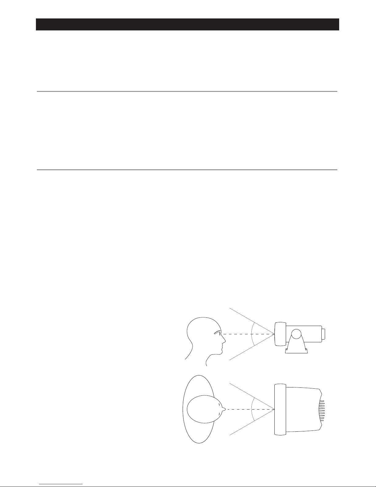
The VHF has a large LCD screen
with an optimum viewing angle
of approx. +/-20 deg. Ensure
the chosen location provides
a suitable view of the display.
Ideally, the user should be directly
in front of the display or no more
than +/-20 deg from the front of
the display.
Note: If unsure, temporarily power
up the radio and check for a
suitable location.
20˚
20˚
20˚
20˚
Side
Top
6 EAGLE - EVR-150 Installation and Operation Instructions
Checklist
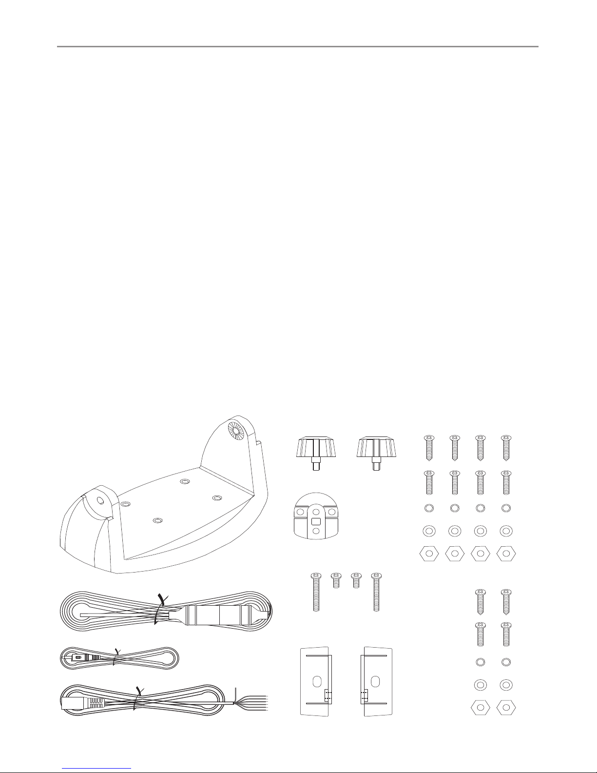
The following items should be supplied in the box. Check before starting the installation and
contact your dealer if an item is missing.
NOTE: An antenna is NOT provided. Consult your Eagle dealer for advice if necessary.
1
3
4
2
6
5
7
8
9
10
11
12
13
14
15
16
17
18 & 19
1. Mounting gimbal for the VHF radio
2. Power supply cable with inbuilt 7 Amp
fuse
3. External speaker connection cable with
white (+) wire and black (-) wire
4. GPS/COM connection cable
5. Two mounting knobs
6. Microphone bulkhead mount
7. Four self-tapping screws for the mounting
gimbal
8. Four flat screws for the mounting gimbal
9. Four spring washers for the mounting
gimbal
10. Four plain washers for the mounting
gimbal
11. Four nuts for the mounting gimbal
12. Two self-tapping screws for the
microphone bulkhead mount
13. Two flat screws for the microphone
bulkhead mount
14. Two spring washers for the microphone
bulkhead mount
15. Two plain washers for the microphone
bulkhead mount
16. Two nuts for the microphone bulkhead
mount
17. Two flush-mount brackets for recessed
installation
18. Two M5x32 screws for recessedinstallation
19. Two M5x10 screws for recessed installation
20. Two plastic stoppers for the recessed
installation (not pictured)
21. Installation template (not pictured)
22. One 7 Amp spare fuse (not pictured)
in case of accidental reverse of battery
polarity
23. Base unit and microphone (not pictured)
7EAGLE - EVR-150 Installation and Operation Instructions
Gimbal Installation
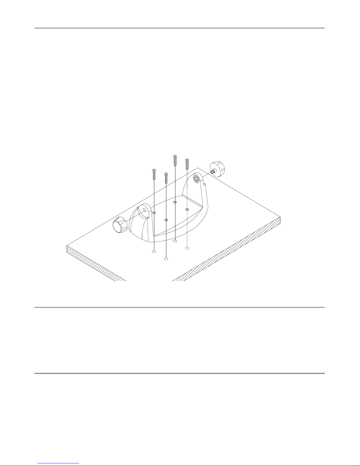
1. Hold the mounting gimbal at the chosen location and use a soft pencil to mark the
screw hole positions onto the mounting surface.
2. If you can’t reach behind the mounting surface to attach the nuts, use the self-tapping
screws instead of the flat screws shown in the picture. If you’re drilling into fiberglass, use
a drill bit smaller than 3/16” (5mm) to drill the pilot holes.
Otherwise, drill the four screw holes where marked, using a 3/16” (5mm) drill bit. Drill
completely through the mounting surface.
3. Use a Philips screwdriver and the set of four flat screws, spring washers, plain washers,
and nuts to attach the mounting gimbal to the location site.
4. Slide the radio into the mounting gimbal.
5. Insert the two mounting knobs through the holes and tighten them sufficiently to hold
the radio at the desired viewing angle.
Change the Viewing Angle
The viewing angle on the gimbal mount has a 20º tilt range. To change the current viewing
angle on the gimbal mount:
1. Support the radio, then cautiously loosen the mounting knobs until the radio can be
moved.
2. Re-position the radio then tighten the mounting knobs again.
Recessed Installation
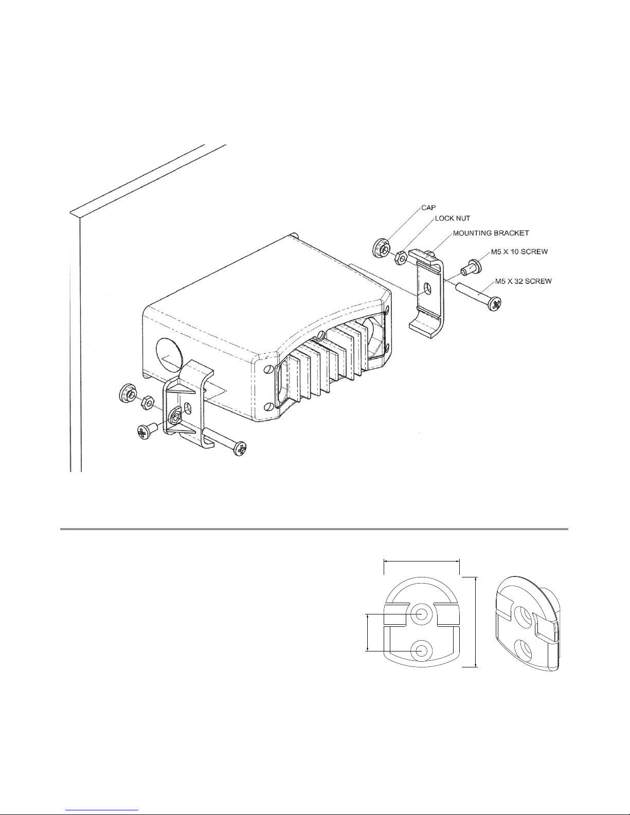
1. Tape the installation template onto the chosen location site.
2. Cut out the area marked by the solid dark line. (The dashed line indicates the total area that
will be ed by the radio fascia after installation.)
3. Remove the installation template and slide the radio into the cavity.
4. Working from the rear of the bulkhead, align the racheted outstand on each side of the
radio with the central hole in each mounting bracket.
8 EAGLE - EVR-150 Installation and Operation Instructions
5. Use the two short M5x10 screws to screw the mounting brackets to the sides of the
radio.
6. Screw each M5x32 screw through the screw hole in the mounting bracket, then attach
the stopper. If your bulkhead exceeds 0.51” (13mm), the stopper can be discarded if
necessary.
7. Tighten the M5x32 screws until the radio is held firmly against the rear of the bulkhead.
Install the Microphone Bulkhead Mount
1. Hold the microphone bulkhead mount at the
chosen location and use a soft pencil to mark
the screw hole positions on the mounting
surface.
Ensure that the microphone curly cable will
comfortably reach this location BEFORE you drill.
2. Drill the two pilot screw holes where marked.
3. Use a short length Philips screwdriver and the
set of two flat screws, spring washers, plain
washers, and nuts to secure the microphone
bulkhead mount at the location
site.
4. Hang the microphone on its mount.
MM
MM
MM
MM
MM
MM
9EAGLE - EVR-150 Installation and Operation Instructions
Fix the DSC label
Connect the Radio Cables
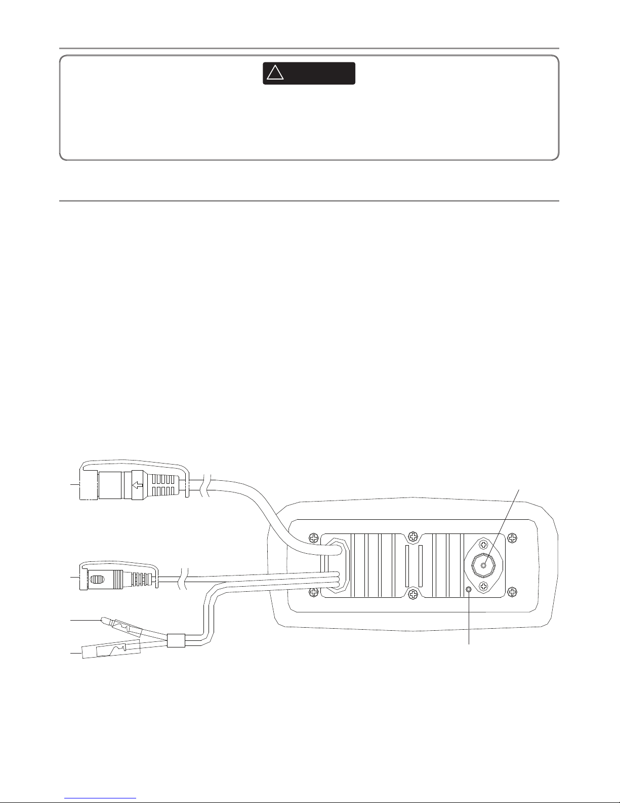
The connectors are on the rear of the base unit, as follows:
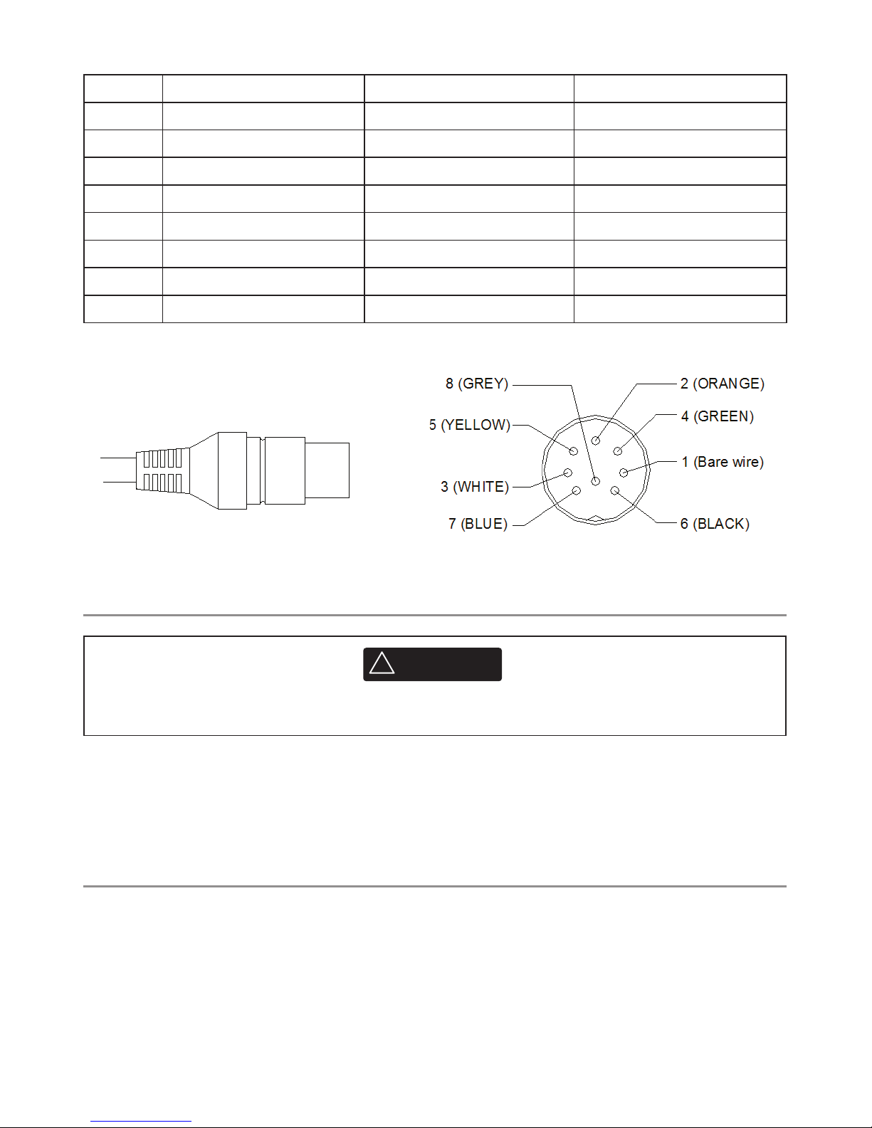
1. GPS/COM connector. For connection to GPS device via NMEA. See the following table
for wiring and color codes. (If you’re not using this, be sure to put the protective cap
securely over the connector to protect it from moisture and dust.)
2. External Speaker connector. Plug the external speaker cable jack into the connector
BEFORE powering on the radio. Use a 4 Ohm 4 Watt external speaker.
3. RED Power wire. Connect this to the POSITIVE (+) battery terminal. Check that a 10 Amp
fuse is installed on this power cable close to the battery.
4. BLACK Power wire. Connect this to the NEGATIVE (-) battery terminal.
5. ANT. A radio antenna is not supplied. A suitable radio antenna must be mounted
and connected before operating the EVR-150 radio. Consult your dealer for advice if
necessary.
6. GND. A ground connection is not usually required.
1
2
3
4
5
6
CAUTION
!
!
CAUTION
DANGER
WARNING
A DSC warning label is supplied with the EVR-150. To comply with FCC regulations, this
warning label must be affixed in a location that is clearly visible from the operating
controls of this Eagle radio. Make sure that the chosen location is clean and dry before
applying this label.
10 EAGLE - EVR-150 Installation and Operation Instructions
Set Up the Radio
The user MMSI is a unique nine digit number, similiar to a personal telephone number. It is
used on marine transceivers that are capable of using DSC (Digital Select Calling).
If you don’t have a user MMSI contact the appropriate authorities in your country. If you’re
unsure who to contact, consult your Eagle dealer.
Enter Your User MMSI
Refer to 4.2 Enter your user MMSI on page 29.
Pin WIre Function Notes
1Red No connection (Not used)
2Orange No connection (Not used)
3White Program/clone (Not used)
4Green NMEA IN (-) (From GPS)
5Yellow NMEA IN (+) (From GPS)
6Black No connection (Not used)
7Blue No connection (Not used)
8Grey No connection (Not used)
Wiring for GPS/COM connector
!
WARNING
You can’t make any DSC transmissions until you’ve obtained a user MMSI and entered it into
your EVR-150.
Table of contents