Druck UPS-III User manual


Copyright 2003 Baker Hughes Company.
English–UPS-III Instruction Manual | 1
Introduction
The Druck UPS-III Intrinsically Safe Loop Calibrator can supply
power (source mode) and produce readings (measure mode) to
perform field calibrations on 2-wire devices. The set-up menu
enables the user to “source” or “measure” in either voltage or
current and to perform continuity tests. These instructions detail
the requirements and operation of the UPS-III Intrinsically Safe
Loop Calibrator in a hazardous area. Read the whole publication
before starting.
Safety
The UPS-III has been designed to be safe when operated using
the procedures detailed in this manual. Do not use this equipment
for any other purpose than that stated, the protection provided by
the equipment may be impaired.
Before installing and using the UPS-III, read and understand all
the related data. This includes: all local safety procedures and
installation standards, and this document.
Before starting an operation or procedure, use only approved
engineers who have the necessary skills (if necessary, with
qualifications from an approved training establishment). Follow
good engineering practice at all times.
Repair
Do not do repairs to this equipment. Return the equipment to the
manufacturer or an approved service agent.

Copyright 2003 Baker Hughes Company.
2 | UPS-III Instruction Manual–English
Symbols
Power Supply
The power supply for this loop calibrator can be the internal non-
rechargeable batteries or an external universal power supply unit,
Druck accessory IOPSU-1.
Batteries
Use only 4 xAA LR6 manganese alkaline primary cells.
Symbol Description
This equipment meets the requirements of all relevant
European safety directives. The equipment carries the CE
mark.
This symbol, on the equipment, indicates a warning and that
the user should refer to the user manual.
Ce symbole, sur l’instrument, indique que l’utilisateur doit
consulter le manuel d’utilisation. Ce symbole, dans le manuel,
indique une situation dangereuse.
Do not dispose of this product as household waste. Use an
approved organization that collects and/or recycles waste
electrical and electronic equipment. For more information,
contact one of these:
- Our customer service department: Druck.com/essential
- Your local government office.
CAUTION Do not mix cell types. Do not mix old and
new cells.
Remove cells from the unit when placed in storage for
an extended period of time.
If a cell has leaked return the unit to an approved
Druck Service Centre.

Copyright 2003 Baker Hughes Company.
English–UPS-III Instruction Manual | 3
1. Guide to Supply and Input/Output
2. Operation
2.1 Keys
The key switches the loop calibrator on
and off. Press and hold for 2 seconds.
The key changes the measure or source
operating mode. Pressing the keys
makes menu selections, sets numerical
values and controls step and ramp functions
(up/down).
The select advanced functions
shown on the bottom of the display. When no key is pressed for
10 minutes, the loop calibrator times out and switches off. To
Table 1: Key to Entity Parameter Table Conditions
Condition Description
&
Current measurement between mA and COM with external
24V. This mode of operation inserts the apparatus in the
current loop by breaking into the circuit and connecting mA
(positive) and COM (negative) into the circuit.
Current measurement between mA (24V) and mA with
internal 24V. Terminal mA (24V) provides the source of
power to supply remote sensor. Special condition for safe
use - remote sensor MUST be isolated from all other sources
of power.
Voltage measurement between V and COM.
Continuity measurement between V and COM. Special
condition for safe use - remote sensor MUST be isolated
from all other sources of power.
Current generation between mA and COM with external
24V. This mode of operation inserts the apparatus in the
current loop by breaking into the circuit and connecting mA
(positive) and COM (negative) into the circuit.
Current generation between mA (24V) and mA with internal
24V. Terminal mA (24V) provides the source of power to
supply the remote sensor. Special condition for safe use -
remote sensor MUST be isolated from all other sources of
power.
MODE
F2
F1
SPAN CHECK
MODE
F2F1

Copyright 2003 Baker Hughes Company.
4 | UPS-III Instruction Manual–English
disable this automatic time out, select Aut power down in the
set-up menu.
2.2 Operating Modes
Pressing switches the instrument on and the display shows
the start-up sequence. Pressing , at this time, the display
shows the information screen:
Pressing , at this time, the display shows the set-up screen:
The calibrator can be used in two modes measure or source.
2.2.1 Measure Mode
The display shows the measured value; depending on the
settings made in set-up and advanced settings:
When measuring current pressing enables linear or flow,
pressing enables mA or % (value of 4 to 20 mA or 0 to
20 mA).
F1
F1
Information
Serial number
VERSION
CAL. DATE
HART
BATTERY
F2
adjust
adjust
4-20mA/0-20mA
mA/%
ON/OFF
ON/OFF
menu
menu
F1
F2
Copyright 2003 Baker Hughes Company.
English–UPS-III Instruction Manual | 5
When measuring voltage pressing changes the resolution
between 0.00 V and 0.000 V.
To measure continuity the displays shows an open or closed
switch symbol with an audible signal on switch closure.
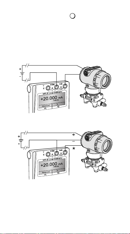
Connect the calibrator to the device to be tested:
Measure mA
Press the mode key and select [Measure mA]. An external power
supply supplies a maximum of 60 V for the loop. The calibrator
measures the current of the loop.
Measure mA
Closed loop current measurement from transmitter test terminal.
F2

Copyright 2003 Baker Hughes Company.
6 | UPS-III Instruction Manual–English
Measure mA with 24V
Press mode key and select [Measure mA and 24V]. The
calibrator supplies 24 V (maximum) for the loop, maximum
24 mA.
Measure Volts
Press mode key and select [Measure Volts], measure range
60 V, maximum impedance 1 Mohm.
Continuity Test
Press mode key and select [Continuity Test]. Pressing
switches the audible signal on/off.
F2

Copyright 2003 Baker Hughes Company.
English–UPS-III Instruction Manual | 7
2.2.2 Source Mode
The display shows the source value in mA or % value of 4 to
20 mA or 0 to 20 mA, linear or flow depending on the settings
made in set-up and advanced settings.
Source mA
Press mode key and select [Source mA]. The calibrator supplies
maximum output of: 24 mA; Vmax =60 V; receiver input
Rmax =1kΩ.
Source mA with 24V
Press mode key and select [Source mA and 24V]. The calibrator
supplies loop power of: 24 V and 24 mA.
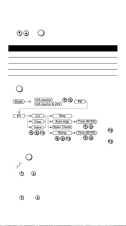
2.3 Advanced Options in a Source Mode
Press the key and select mA Source or mA Source & 24V.
Use and (Enter) to select the function.
Press the key (Advanced) and the display shows:
5PD[ Nȍ
I/P
MODE
F2
F1
Copyright 2003 Baker Hughes Company.
8 | UPS-III Instruction Manual–English
• ‘Linear’ simulates linear transmitters.
• ‘Flow’ simulates flow transmitters.
• ‘Valve’ simulates valve control signals.
Use and (Enter) to select the Advanced option:
Note: Ramp function not available for valve selection.
Use to quit. The display returns to the selected source mode
with the advanced setting available.
2.3.1 Example Operation
Press the key to switch the advanced setting on and off:
e.g. on or off
Press or to:
a. step the output up or down.
b. step the span check maximum or minimum.
c. start the “ramp”.
Press then to start:
a. continuous auto-step.
or
Table 2: Advanced Options
Option Description
Step 25% steps for linear and flow - fixed values for valve.
Auto-step The same as step with a timed step interval.
Span Check Step between 4 (or 0) mA and 20 mA.
Ramp Automatic ramp between 4 (or 0) mA and 20 mA.
F2
F1
select Enter
Advanced
select
select
Adjust ±1 second
Adjust ±1 second
F2
Table of contents
Other Druck Test Equipment manuals

Druck
Druck TRX User manual

Druck
Druck UPS-III-IS User manual

Druck
Druck DPI 610E User manual

Druck
Druck DPI 610 IS User manual

Druck
Druck PV 62XG User manual

Druck
Druck DPI620 Genii User manual

Druck
Druck DPI 620 Genii Instruction Manual

Druck
Druck InstruMetrics ADTS542F Setup guide

Druck
Druck ADTS 403R Use and care manual

Druck
Druck DPI 841 User manual


