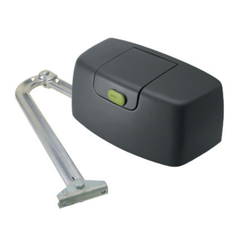
DoorHan SECTIONAL-500PRO User manual

OPERATOR
SECTIONAL-500PRO/ 750PRO
© DoorHan, 2014
Installation and Operating Manual
2
2
4
5
6
8
12
13
13
CONTENTS
GENERAL INFORMATION
SAFETY INSTRUCTIONS
OPERATOR UNIT
OPERATOR INSTALLATION
ELECTRICAL CONNECTIONS
MANUAL OPENING
MAINTENANCE
TROUBLESHOOTING
APPENDIX 14
Actual versions
soft - v 1.0
pcb - v 1.0

2
GENERAL INFORMATION
CONTENTS
1. GENERAL INFORMATION ............................................................................2
1.1. Specifications ................................................................................3
1.2. Operator package ..............................................................................3
1.3. Track .......................................................................................3
2. SAFETY INSTRUCTIONS ............................................................................4
3. OPERATOR UNIT ..................................................................................5
3.1. Overall dimensions ............................................................................5
3.2. Drive device ..................................................................................5
4. OPERATOR INSTALLATION ..........................................................................6
4.1. Tools .......................................................................................6
4.2. Requirments to door installation ..................................................................6
4.3. Connection of operator and guide .................................................................6
4.4. Track installation ..............................................................................7
5. ELECTRICAL CONNECTIONS .........................................................................8
5.1. Control block specifications .....................................................................8
5.2. Control block wiring diagram ....................................................................8
5.3. Operator programming .........................................................................8
1. Operator control keys .........................................................................8
2. Preparation .................................................................................9
3. Upper door position ...........................................................................9
4. Low door position .............................................................................9
5. Automatic force setup ..........................................................................9
6. Force limit setup ..............................................................................9
7. Absolute cycle counter ........................................................................10
8. Warning alarm setup ..........................................................................10
9. Automatic closing ...........................................................................10
10. Maintenance counter after 2000 cycles (factory setting: «0» – the function is off) .........................10
11. Completing the programming ..................................................................10
5.4. Remote control programming ...................................................................11
1. To add a remote control .......................................................................11
2. Remote programming for Doorhan remote controllers ................................................11
3. Marking remote control buttons DOORHAN .......................................................11
4. To erase a remote control .....................................................................11
6. MANUAL OPENING ...............................................................................12
7. MAINTENANCE ..................................................................................13
8. TROUBLESHOOTING ..............................................................................13
APPENDIX
..........................................................................................14
1. GENERAL INFORMATION
Electromechanical drive chain type Sectional-500PRO/750PRO is designed to automate everyday balanced sectional doors.
It consists of a mechanical gear and an electric engine with a built-in control unit. The gear and the electric engine are
incorporated into a housing.
It consists of an electromechanical motor reducer, an electronic control unit and an illuminating lamp, incorporated into
a housing. The electric operator is easily secured on a track and mounted to the ceiling, opening of the doors is carried out by
means of a chain/belt gear. The self-locking operator gear ensures mechanical interlocking of the doors, if engine is not functioning,
but in the absence of electric power the manual emergency release allows you to open and to close the doors manually.
For maximum safety, the control unit has force protection.
Besides, optionally, the operator can be equipped by electronic protective sensors, which stop the doors closing, if there are
obstacles or people within the operating range of automatic system.

3
Parameters SE 500PRO SE 750PRO
Power supply 220–240 V
Consumed power 150 W
Waiting mode 6 W
Force 500 N 750 N
Control Stepped (pulse) mode
Motor 24В DC
Opening speed 0,14 m/sec
Door area til 8 m2till 10 m2
Operating temperatures range –20…+55 °С
Fuses Power supply — 2.5 A
Radio control 433,92 MHz
Transmission Chain/Belt
Protection rating IP 20
ПРИВОД
SECTIONAL-500PRO
© DoorHan, 2012
Инструкция по монтажу и эксплуатации
2
2
4
4
4
6
6
8
9
9
10
10
СОДЕРЖАНИЕ
ОБЩИЕ СВЕДЕНИЯ
ПРАВИЛА БЕЗОПАСНОСТИ
УСТРОЙСТВО ПРИВОДА
УСТАНОВКА ПРИВОДА
ЭЛЕКТРИЧЕСКИЕ ПОДКЛЮЧЕНИЯ
ПРОГРАММИРОВАНИЕ ЭЛЕКТРОПРИВОДА
ПРОГРАММИРОВАНИЕ ПУЛЬТА ДУ
РУЧНОЕ ОТКРЫВАНИЕ
ОБСЛУЖИВАНИЕ
ДИАГНОСТИКА НЕИСПРАВНОСТЕЙ
1.1. SPECIFICATIONS
Electric operator Operating manual Guide Curved arm U-shaped bracket
Guide fastening bracket Headroom bracket Straight arm fastening bracket Slotted bushing Fastening set
№ Name Quantity № Name Quantity
1 Electric operator 1 6 Guide fastening bracket 1
2 Operating manual 1 7 Headroom bracket 1
3 Guide 1 8 Straight arm fastening bracket 1
4 Curved arm 1 9 Slotted bushing 1
5 U-shaped bracket 3 10 Fastening set 1
1.2. OPERATOR PACKAGE
When you receive your Sectional-500PRO/750PRO operator, unpack it and check that the operator is not damaged. If any
damages are found, contact the operator supplier.
The operator components included in the standard package are listed in the following table.
Guide model Guide length, L Travel Opening height
SK-3000 chain/belt 3 000 mm 2 300 mm 2 300 mm
SK-3300 chain/belt 3 320 mm 3 100 mm 2 600 mm
SK-3600 chain/belt 3 620 mm 2 800 mm 2 800 mm
SK-4200 chain/belt 4 220 mm 3 400 mm 3 400 mm
SK-4600 chain/belt 4 620 mm 3 800 mm 3 800 mm
1.3. TRACK
GENERAL INFORMATION

4
2. SAFETY INSTRUCTIONS
IMPORTANT! You should observe the safety regulations to preserve people’s health. You must keep the present Manual.
You should follow all the recommendations of the given Manual, as incorrect equipment installation could lead to serious
damages.
The Sectional-500PRO/750PRO operator is designed for automation of residential sectional doors. It should be used only
for the purpose intended; any other use is forbidden.
DoorHan is not liable for personal injuries, if the product was used for purposes other than intended.
Make sure that the doors are balanced and function smoothly before installing the operator.
The installation is to be carried out according to the standards EN 12453 and EN 12445. For providing the required safety
level, these requirements should be observed in non-EU countries.
You should check if the doors conform to the standards EN 12604 and EN 12605 (see documentation on the doors). For
non-EU countries these measures are to be observed for ensuring the normal safety level.
The mechanical door assembly units must conform to the provisions of the standards EN 12604 and EN 12605.
The gate must manually move smoothly all the way, with a force of more than 20 kg.
Before installing the operator, make sure that the mounting location by its climatic conditions corresponds to the
operator’s specifications.
You should not install the equipment in rooms with highly flammable substances or other hazardous media, as this can
result in explosion or fire.
You should use tools, indicated in Section “Tools” of the given Manual, during assembly, installation and adjustment
of the operator.
You should use a stable support when working at height.
The operator is allowed to install at more than 2.5 m height.
You should use hand and face protection when drilling holes.
You should use metal goods from the operator package or other goods equivalent to them for fastening the product.
You should power off when performing installation, cleaning or maintenance of the operator.
When mounting the operator on doors with the infitting pass door, it is necessary to install an additional safety device,
which prevents the operator activation, when the door is open.
Make sure, that there will not be trapping of articles between movable and fixed elements of the operator when the doors
move.
You should use additional DoorHan accessories, since the accessories of third party manufacturers can damage the
automatic system.
DoorHan is not liable for unstable work of the automatic system, if you use safety devices and accessories, produced by
other manufacturers without securing approval of DoorHan.
You should not leave electric engines in a released state. This can lead to uncontrolled movement of the door wings and,
as a result, to their damage.
You should not use the operator, if it is necessary to repair or to adjust the equipment, since defects during the assembly
of the operator or incorrectly installed doors can result in injury.
DoorHan is not liable, if the product is not correctly installed or is damaged during operation.
The electric operator is not equipped with the stationary power cord; therefore mains supply is to be fed to the automatic
system via an automatic switch with a distance between the adjacent contacts minimum 3 mm. It is recommended to use
double pole circuit breaker 10 A.
Make sure, that there are no foreign bodies within the operating range of the electric operator before its start.
You should not introduce changes, not stated in the given Manual, into the automatic system.
You should remove the product package and dispose of it. You should not leave the packaging materials within the reach
of children.
You should not allow children to play in the door movement area during the operator operation. All remote control panels
and also stationary control buttons must be absolutely inaccessible for possible use by children.
It is allowed to drive in and to pass only when the doors do not move and the operator is switched off.
The contents of the Manual could not serve as a basis for laying claims of any kind.
The manufacturer reserves the right to introduce modifications into the structure and to improve it without prior notice.
IMPORTANT! For safe and correct work of the operator it is necessary to install a mechanical stop to limit the door leaf
motion.
SAFETY INSTRUCTIONS
The Installation and configuration of the actuator must only be carried out by qualified specialists.
After installing the drive, test force according to standards EN 12445 and EN 12453.

5
3. OPERATOR UNIT
267
92
170
WARNING! RISK OF INJURY!
Have a qualified technician lay the cables 230 V AC. The cables must be laid in protective corrugated tubes. In case
of supply cable damage, use the suitable type of the cable.
Cables needed for installation of sectional-500 operator and accessories (if available)
Cable 2 × 0.5 mm2 (photocell transmitter)
Cabel 4 × 0.5 mm2 (photocell receiver)
Cable 3 × 1.5 mm2 (power supply)
The cables should be appropriately insulated
1. Display cover
2. Housing cover
3. LED lamp
4. Display
5. Motor reducer
6. Control board
7. Housing
8. Reference point microswitch
9. Splined bushing
1
2
3
4
5
6
7
8
9
3.1. OVERALL DIMENSIONS
3.2. DRIVE DEVICE
OPERATOR UNIT

6
4.3. CONNECTION OF OPERATOR AND GUIDE
1. Put the operator bushing (4) on the shaft (5).
2. Insert the operator unit into the hole on the
guide (3).
3. Fasten the operator with U-brackets (2) and
tapping screws (1).
1. Tapping screws
2. U-bracket
3. Guide
4. Bushing
5. Motor shaft
4.2. REQUIRMENTS TO DOOR INSTALLATION
Prior to installation check if the door is
properly balanced and moves smoothly when
automatically operated.
Make sure, that minimal clearance between
the ceiling and the top point, when the door is
moving, is not less than 45 mm (pic. 1).
Check, that the door leaf top roller is in the
horizontal part of the guide rail, when the door
is completely closed (pic. 2).
Mount the door control panel at a height not less
than 1.5 m close to the door.
Pic. 1 Pic. 2
45 mm
1. Set of spanners
2. Set of slotted and cross screwdrivers
3. Set of drills for metal
4. Set of drills for concrete
5. Pliers
6. Hacksaw for metal
4. OPERATOR INSTALLATION
4.1. TOOLS
7. Electric drill
8. Tape measure (folding rule)
5
4
3
1
2
OPERATOR INSTALLATION

7
4.4. TRACK INSTALLATION
The operator suspension height is determined by the maximum lift of upper edge of the door leaf. After preliminary assembly
(see p. 4.3) you can start to install the track:
1. If it is required to shorten a guide, it is necessary to fulfill operations, described in Appendix 1.
2. You should mark a vertical line, corresponding to the horizontal door centre (fig. 5).
3. You should place a lintel mounting bracket (1) in such a way that the distance from upper edge of the open door leaf to lower
edge of the track amounted to minimum 10 mm (fig. 5.2) and fix it to the lintel using self-tapping screws (2) (fig. 5.1).
4. You should fasten the track (3) and the lintel mounting bracket by means of a track fixation bolt (4) (fig. 5.3).
5. You should install a U-shaped bracket (5) on the track approximately at a distance 2/3 L and attach it to the ceiling (fig. 5.4).
6. You should install track mounting brackets (6) on the track approximately at a distance 1/3 L and attach them to the
ceiling (fig. 5.5).
7. You should install a rod-to-leaf mounting bracket (7) in the middle of the upper aluminium profile of the door leaf and fix
it using self-tapping screws (8) (fig. 5.6).
8. You should attach a cranked rod (9) to the rod mounting bracket and fix it by means of a pin axle (10) (fig. 5.7).
It is allowed not to mount the cranked rod, if α angle is observed.
1
1. Lintel mounting bracket
2. Anchor bolt
3. Track
4. Track fixation bolt
5. U-shaped bracket
6. Track mounting bracket
7. Rod-to-leaf mounting bracket
8. Screw 6x15
9. Cranked rod
10. Pin axle
10
23
4
6
9
10
Pic. 5
5.1 5.2 5.3
5.5 5.7
α
Door
Wall
B/2
B
α
30° < α < 60°
L
∼1/3L
∼2/3L
5
5.4
7
8
5.6
OPERATOR INSTALLATION

8
1. OPERATOR CONTROL KEYS
5.3 Operator programming
5.2 Control block wiring diagram
WARNING! The cable wires must be protected from contact with any rough or sharp parts. All connections shall be made
only when power is off.
Parameters Units
Power supply 180-240 V/50-60 Hz
Power supply of accessories 24 V DC
Maximal current of accessories 200 mA
Working temperature range –20…+55 °C
Radio control frequency 433,92 MHz
Operating logics Automatic/Semi-automatic
Connectors Open button/Safety devices
Lamp turn-on time 3 min
Fuse type Quick cutoff fuse, 230 V, 2.5 А
5. ELECTRICAL CONNECTIONS
5.1 Control block specifications
1. Radio code record button — “R”
2. Display
3. Setting selection buttons — “+”, “–”
4. Programming button — “P”
+
-
P
R
13
4
2
PE
12V
ANT
GND
IR
GND
24V
NO
NC
COM
COM NO NC
DOOR
STOP
.. ... .....
......
Antenna
Safety devices with normally
closed contacts (NC)
LAMP
220V
To lightening lamp
(built in operator housing)
Supply voltage of motor
12 V AC (after transformer)
LED3
GND
VCC
(+24)
CON2
LED2
GND
VCC
(+24)
CON1
LED1
IR
COM
NO NC
Photosells
BATTERY 24VLAMP
24V DC
Black
Observe the polarity!
Red
+–+–
ELECTRICAL CONNECTIONS

9
2. PREPARATION
Block the carriage.
Turn on power, the indicator of the operator will light, sound signal will be heard.
If programming has not been completed, the settings will not be stored. If there is a mistake in one of the settings, you can
turn off power and reprogram.
The setting will be stored only when you program the UPPER door position. The upper position shall be programmed
before setting the lower door position.
3. UPPER DOOR POSITION
4. LOW DOOR POSITION
The setting will be stored only when you program the LOW door position.
5. AUTOMATIC FORCE SETUP
6. FORCE LIMIT SETUP
Press and hold
down the button «P»
during about 5 sec
«1» will light When pressing «+» and «-», set the door panel into
upper position required.
Press «P»,
«1» will flash
Press «+» «2» will light When pressing «+» and «-», set the door panel into
closed position.
Press «P», «2» will
flash
Press «P», «3»
will flash
By default, the operator is set on the 3rd sensitivity stage; usually the customers do not need to change these settings.
Press «P» to save
the information
Press «P» to save
the information
After finishing the automatic force setup, a beep will sound, and the program comes out of programming
mode automatically.
After performing these setups, the programming can be finished; all other parameters have factory settings.
When pressing «+» and «-», select an operator force function value: «1» –
minimum force value, «6» – maximum force value. Press «P» to save the
information
Press «P»
to save the information
The door function may be disrupted by setting
maximum or minimum sensitivity value!
Factory
setting
Press «+» «4» will light,
press «P»
again
Нажимая «+» и «–», установите полотно в необходимое
верхнее положение
Нажмите «Р» для
сохранения информаци
Нажмите «+» Нажимая «–» и «+», установите полотно ворот в закрытое
положени е
Нажмите «Р» для
сохранения информации
замигает
Press «+»,
«3» will light
The door automatically performs the full cycle (opening/closing), then a beep will sound,
and the program comes out of programming mode automatically «3» will light
Нажмите «+» —
загорится «3»
Ворота автоматически совершат полный цикл (открытия/закрытия) после чего раздастся
короткий звуковой сигнал и программа автоматически выйдет из режима программирования
Нажмите «+»
OPERATOR PROGRAMMING

10
Нажмите «+» —
загорится «8»
P
+
-
Нажмая «+» или «–» выберите значение
функции: «0» — выкл., «1» — вкл.
Нажмите «P»
Нажмите «P» для сохранения
информации
P
+
-P
+
-
Нажмите «P»
P
+
-
Нажмите «+» —
загорится «7»
7. ABSOLUTE CYCLE COUNTER
8. WARNING ALARM SETUP
9. AUTOMATIC CLOSING
Press “P”
10. MAINTENANCE COUNTER AFTER 2000 CYCLES (FACTORY SETTING: «0» – THE FUNCTION IS OFF)
Press «+» «5» will light, press
«P»
The 1st digit will be
displayed
Press «+» «6» will light,
press «P»
When pressing «+» and «-», select a function
value: «0» – off, «1» - on
Press «+», «
7» will light
Press «P» When pressing «+» and «-», select a function value: «0» -
no automatic closing, «1» - pause 30 sec, «2» - pause
60 sec ..., «8» - pause 240 sec.
Press «P» to save the
information
When pressing «+» and «-», select a function
value: «0»– off, «1» – on
Press «+»,
«8» will light
When entering the 5th point of menu, two digits will be displayed sequentially. After having displayed the digits, the
program returns to main menu.
The first digit – tens, the second digit – units.
The value received is multiplied by 1000 to receive information on amount of cycles driven by the operator.
The 2nd digit will be
displayed
Press «P» to save the
information
Press «P» to save the
information
In the case you forgotten to close the door, after 10 minutes a warning alarm will sound. This signal will be turned off
automatically after the door will be closed. The factory setting of this function is “0” – the function is off.
11. COMPLETING THE PROGRAMMING
Press «+» or «-», select «1». Press and hold down «P» until «0» appears on the display. The programming is complete.
OPERATOR PROGRAMMING
This manual suits for next models
1
Table of contents
Other DoorHan Gate Opener manuals

DoorHan
DoorHan SWING-4000 User manual

DoorHan
DoorHan SHAFT-120 User manual

DoorHan
DoorHan Sectional-1000 User manual

DoorHan
DoorHan PCB-SH Installation manual

DoorHan
DoorHan SWING-3000 User manual

DoorHan
DoorHan SHAFT-20 User manual

DoorHan
DoorHan SHAFT-30 User manual

DoorHan
DoorHan SHAFT-50 User manual

DoorHan
DoorHan SECTIONAL-800PRO-CE User manual

DoorHan
DoorHan Sectional-750 User manual