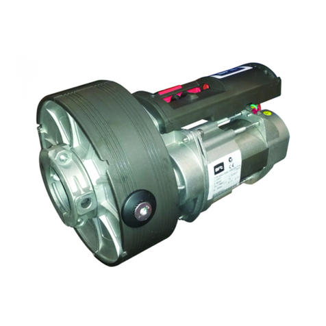
DITEC Sprint User manual

Ditec SPRINT
Automation for swing
doors
(translation of the original instructions)
Technical Manual
www.ditecautomations.com
IP2185EN • 2022-06-28
Last version of this manual

2
IP2185EN
Key
This symbol indicates instructions or notes regarding safety, to which special atten-
tion must be paid.
This symbol indicates useful information for the correct functioning of the product.
Contents
General safety precautions .........................................................................................................................................3
EC Declaration of Incorporation ...............................................................................................................................5
1. Technical specifications ...................................................................................................................................6
1.1 Machinery Directive .................................................................................................................................................7
1.2 Dimensions ...............................................................................................................................................................7
2. Standard installation ......................................................................................................................................8
3. Main components ..............................................................................................................................................9
4. Mechanical installation .................................................................................................................................10
4.1 Removing the casing ...........................................................................................................................................10
5. Installation with SBS sliding arm ...............................................................................................................11
6. Installation with SBA articulated arm .............................................................................................................12
7. Installation with SPRINTBRAS 3-lever articulated arm ...........................................................................13
8. Electrical connections ......................................................................................................................................14
8.1 Electrical connections for 230 V~ power supply .................................................................................................14
8.2 Electrical connections for 24 V power supply ..........................................................................................15
8.3 Electromagnetic emissions ....................................................................................................................................15
9. Connecting the power supply .........................................................................................................................16
10. Commands ......................................................................................................................................................16
10.1 Testable safety devices .........................................................................................................................................16
11. Outputs and accessories ...............................................................................................................................17
11.1 Function selector button ....................................................................................................................................18
11.2 Example of installation with function selector COMH- COMK ................................................................19
11.2.1 Connections PASS24 .............................................................................................................................................................19
11.2.2 Connections REM ...................................................................................................................................................................19
12. Adjustments .....................................................................................................................................................20
12.1 Enabling procedure ..................................................................................................................................................20
12.2 Dip-switches .............................................................................................................................................................20
12.3 Trimmers ..................................................................................................................................................................21
12.4 Signals ......................................................................................................................................................................21
13. Door requisites for Low Energy use .............................................................................................................22
14. Start-up ...........................................................................................................................................................23
15. Troubleshooting ..............................................................................................................................................24
16. Routine maintenance plan ............................................................................................................................25

3
IP2185EN
This installation manual is intended for qualified personnel only •Instal-
lation, electrical connections and adjustments must be performed by
qualified personnel, in accordance with Good Working Methods and in
compliance with the current regulations • Read the instructions carefully
before installing the product. Wrong installation could be dangerous •
Before installing the product, make sure it is in perfect condition •
The packaging materials (plastic, polystyrene, etc.) should not
be discarded in the environment or left within reach of children,
as they are a potential source of danger • Do not install the product
in explosive areas and atmospheres: the presence of inflammable
gas or fumes represents a serious safety hazard • Make sure that
the temperature range indicated in the technical specifications is
compatible with the installation site • Before installing the motoriza-
tion device, make sure that the existing structure, as well as all the
support and guide elements, are up to standards in terms of strength
and stability. Verify the stability and smooth mobility of the guided
part, and make sure that no risks of fall or derailment subsist. Make
all the necessary structural modifications to create safety clearance
and to guard or isolate all the crushing, shearing, trapping and ge-
neral hazardous areas • The motorization device manufacturer is
not responsible for failure to observe Good Working Methods when
building the frames to be motorized, or for any deformation during
use • The safety devices (photocells, safety edges, emergency stops,
etc.) must be installed taking into account the applicable laws and
directives, Good Working Methods, installation premises, system
operating logic and the forces developed by the motorized door or
General safety precautions
ATTENTION! Important safety instructions.
Please follow these instructions carefully. Failure to observe
the information given in this manual may lead to
severe personal injury or damage to the equipment.
Keep these instructions for future reference.
This manual and those for any accessories can be
downloaded from www.ditecautomations.com.

4
IP2185EN
gate • The safety devices must protect against crushing, cutting,
trapping and general danger areas of the motorized door or gate.
Display the signs required by law to identify hazardous areas. Each
installation must bear a visible indication of the data identifying the
motorized door or gate • Before connecting the power supply, make
sure the plate data correspond to those of the mains power supply.
An omnipolar disconnection switch with a contact opening distance
of at least 3mm must be fitted on the mains supply. Check that there
is an adequate residual current circuit breaker and a suitable over-
current cutout upstream of the electrical installation in accordance
with Good Working Methods and with the laws in force • When re-
quested, connect the motorized door or gate to an effective earthing
system that complies with the current safety standards • Before
commissioning the installation to the end user, make sure that the
automation is adequately adjusted in order to satisfy all the functio-
nal and safety requirements, and that all the command, safety, and
manual release devices operate correctly •
During installation, maintenance and repair operations, cut
off the power supply before opening the cover to access the
electrical parts
•
The protection cover of the operator must be
removed by qualified personnel only.
The electronic parts must be handled using earthed antista-
tic conductive arms. The manufacturer of the motorization
declines all responsibility if component parts not compatible with
safe and correct operation are fitted • Only use original spare
parts for repairing or replacing products • The installer must
supply all information concerning the automatic, manual and
emergency operation of the motorized door or gate, and must
provide the user with the operation and safety instructions.

5
IP2185EN
EC Declaration of Incorporation
We:
ASSA ABLOY Entrance Systems AB
Lodjursgatan 10
SE-261 44 Landskrona
Sweden
Declare under our sole responsibility that the type of equipment with name:
Ditec SPRINTV, Ditec SPRINTP, Ditec SPRINTPN, Ditec SPRINTL - swing door operators
Comply with the following directives and their amendments:
2006/42/EC Machinery Directive (MD) for the following essential health and safety
requirements: 1.1.2, 1.1.3, 1.2.1, 1.2.2, 1.2.3, 1.2.4.2, 1.2.6, 1.3.9, 1.4.3, 1.7.2,
1.7.3, 1.7.4, 1.7.4.1, 1.7.4.2.
2014/30/EU Electromagnetic Compatibility Directive (EMCD)
2011/65/EU Restriction of hazardous substances (RoHS 2)
2015/863/EU Restriction of hazardous substances (RoHS 2 Amendment)
Harmonized European standards that have been applied:
EN 16005:2012
EN 60335-1:2002 + A11:2004 + A1:2004 + A12:2006 + A2:2006 + EC:2007 + A13:2008 + A14:2010 + A15:2011
EN60335-2-103:2005-07 +A11:2009-07
EN 61000-6-3:2007 + A1:2011
EN 61000-6-2:2005
EN 55014-1:2006 + A1:2009 + A2:2011
EN ISO 13849-1:2006
The manufacturing process ensures the compliance of the equipment with the technical file.
The equipment must not be used until the final installed automatic entrance system has been
declared in compliance with the Machinery Directive 2006/42/EC.
Responsible for technical file:
Matteo Fino
BSP Ind channel & Gate Automation
Ditec S.p.A.
Largo U. Boccioni, 1
21040 Origgio (VA)
Italy
Signed for and on behalf of ASSA ABLOY Entrance Systems AB by:
Place Date Signature Position
Origgio 2022-06-28 Matteo Fino
Head of Ind channel & Gate Automation
© ASSA ABLOY, All rights reserved

6
IP2185EN
1. Technical specifications
SPRINT PN - P - V SPRINT L
Power 230 V~ - 50 / 60 Hz 24 V (to be protected with an
external fuse)
Power 0.5 A 3 A
Power 120 W 120 W
Torque 25 Nm 25 Nm
Insulation class Class 2 /
Opening time min 3 s /90°
max 6 s /90°
min 3 s /90°
max 6 s /90°
Closing time min 4 s /90°
max 7 s /90°
min 4 s /90°
max 7 s /90°
Intermittence S3= 80% S3= 80%
Type of operation Motor opening
Motor closing
Motor opening
Motor closing
Max load (door wing 90cm) 110 kg 110 kg
Max load (door wing 1.2m) 70 kg 70 kg
Temperature min -20 °C max +55 °C min -20 °C max +55 °C
Degree of protection IP30 IP30
Control panel EL38 EL38
Power supply AL05 /
F1 fuse F1A /
Motor output 24 V 3.5 A 24 V 3.5 A
Power supply for accessories 24 V 0.3 A 24 V 0.3 A
Minimum number of manoeuvres
in AVERAGE conditions of use 1.000.000 cycles 1.000.000 cycles
Operating instructions
-
20
40
60
80
100
120
0,7 0,8 0,9 1,0 1,1 1,2
DOOR WEIGHT [kg]
DOOR WIDTH [m]
SBA
SBS
0
1
2
3
4
5
6
7
7
45
62
3
1
10 20 30 40 50 60 70 80 90 100110
DOOR WEIGHT [kg]
VM adjustment

7
IP2185EN
1.2 Dimensions
93 450
91 450
445
797975
7,5 60
8,5111 149 168
NOTA: unless otherwise specified, all measurements are expressed in millimetres (mm).
1.1 Machinery Directive
According to the Machinery Directive (2006/42/EC), the installer who motorises a door or gate has
the same obligations as the manufacturer of a machine, and as such must:
- prepare the technical documentation, which must contain the documents indicated in An-
nex V of the Machinery Directive;
(the technical documentation must be kept and made available to the competent national
authority for at least ten years, starting from the date of construction of the motorised door);
- draw up the EC statement of conformity according to Annex II-A of the Machinery Directive
and hand it over to the customer;
- affix the EC marking to the motorised door in accordance with point 1.7.3 of Annex I of the
Machinery Directive.
- ensure compliance of the motorised door or gate with safety regulations, by installing the
necessary safety devices.

8
IP2185EN
2. Standard installation
4
6
6
1
5
7
2
3
A
Ref. Code Description
1SPRINT Automation
2SBA
SBS
SPRINTBRAS
FBA
Articulated movement arm
Sliding movement arm
Articulated movement arm with three levers
End stop for articulated arm
3End stop on the ground
4COMH-COMK Function selector switch
5SPRINTBAT Battery kit
6PASM24W (microwave), or
PASM243 (microwave), or
PASS24 (microwave), or
PASA (infrared)
Opening sensor
PAY ATTENTION TO THE FASTENING POSITION.
7REM90
REM110
Sensor for safe opening and closing
AConnect the power supply to a type-approved omnipolar switch, with a
contact opening distance of at least 3mm (not supplied).
Connection to the mains must be via an independent channel, separate
from the connections to the control and safety devices.
NOTE: the given operating and performance features can only be guaranteed with the
use of DITEC accessories and safety devices.

9
IP2185EN
3. Main components
Ref. Code Description
124V motor with encoder
2EL38 Control panel
3SPRINTBAT Battery kit
4Base plate
5ON/OFF button
6Function selector button [SPRINT V]
7Arm support
8Aluminium casing [SPRINT V]
9Grey plastic casing [SPRINT P-SPRINT L]
Black plastic casing [SPRINTPN]
1
9
2
3
5
7
8
4
6

10
IP2185EN
Check the stability and weight of the door wing. Make sure it moves smoothly, without any friction
(reinforce the frame if necessary).
Any “door closer” mechanisms must be removed or completely annulled.
4. Mechanical installation
4.1 Removing the casing
1
2
WARNING: in the event of installation on doors that divide areas with different pres-
sure levels, check for proper functioning.
Other manuals for Sprint
3
Table of contents
Other DITEC Door Opening System manuals

DITEC
DITEC DAB105 User manual

DITEC
DITEC 94 System manual

DITEC
DITEC CIVIK Series Manual

DITEC
DITEC COM E User manual

DITEC
DITEC entrematic HA8-LP Service manual

DITEC
DITEC ENTREMATIC HA9 User manual

DITEC
DITEC ENTREMATIC HA9 Service manual

DITEC
DITEC Flash C User guide

DITEC
DITEC Sprint User manual

DITEC
DITEC DOD Series Instruction Manual
Popular Door Opening System manuals by other brands

Normstahl
Normstahl IDO7 installation manual

Häfele
Häfele Finetta T 70 VF manual

AGS
AGS D-PL Instructions for fitting, operating and maintenance

Stanley
Stanley MA900ñ Installation and owner's manual

WITTUR
WITTUR Hydra Plus UD300 Instruction handbook

Alutech
Alutech TR-3019-230E-ICU Assembly and operation manual