
dinacell OMEGA NG User manual

OMEGA
/NG
LOAD WEIGHING DEVICE
User manual

User manual OMEGA
/
NG
2
INDEX
1.DESCRIPTION AND MAIN FEATURES ..........................................................3
2.DISPLAY AND CONTROL BUTTONS.............................................................3
3.DIMENSIONS, INSTALLATION AND CONNECTIONS...................................4
4.MENU STRUCTURE ........................................................................................5
5.HOW TO VISUALIZE OR CHANGE PARAMETERS......................................6
6.DEVICE INFO...................................................................................................7
7.SYSTEM CONFIGURATION............................................................................8
8.ALARMS CONFIGURATION..........................................................................10
9.CHAIN COMPENSATION ..............................................................................12
9.1.New Chain Compensation.........................................................................12
9.2.Submenu Chain.........................................................................................12
9.3.Chain Compensation Adjust ......................................................................13
9.3.1.Software Compensation .....................................................................13
9.3.2.Hardware Compensation....................................................................13
9.3.3.Auto-Zeroing Compensation...............................................................14
10.ADDITIONAL FUNCTIONS............................................................................15
10.1.Hold function..............................................................................................15
10.2.Analog output (Optional)............................................................................15
10.3.Cabin Display (Optional)............................................................................16
11.CANOPEN PARAMETERS (ONLY RELEVANT FOR OMEGA-C MODELS )...........16
12.ERROR CODES AND TROUBLESHOOTING ...............................................18
13.ELECTRICAL SPECIFICATIONS ..................................................................18
14.NG CONECTION............................................................................................19
14.1.Wifi NG Connection ...................................................................................19
14.2.Firmware Update .......................................................................................19
15.WIRE ROPE TENSION EQUALAZING..........................................................20
15.1Wire Rope Tension checking Tool.............................................................20
15.2Assistance to the wire rope tension adjustment.........................................21
16.QUICK CONFIGURATION GUIDE.................................................................23

User manual OMEGA
/
NG
3
1. DESCRIPTION AND MAIN FEATURES
OMEGA/NG Unit control is a Load Weighing device of the (NG) New Generation units from
Dinacell Electronic with CanOpen-Lift CIA 417 Integrated.
The Main features of this unit are:
-Measures, monitors and limits load in elevators.
-Up to 12 Individual Rope Tension monitoring.
-Wire Rope Tension adjustment.
-5 Digits display with 4 LEDs for alarm indication and 2 LEDs for Can Status
-Hold Input
-4 Alarms Thresholds (Full Load, Over Load, Zero Cabin, Slack Rope Tension )
-4 Relays output
-0-10v Analog Output
-4-20ma Analog Output
-Cabin Display Output
-CanOpen-Lift CiA 417.
-Software Chain compensation.
-Hardware Chain compensation.
And the new features of Our NG devices
-Remote WIFI Programming( NG )
-USB connection for firmware upgrading.
2. DISPLAY AND CONTROL BUTTONS
Functions of control buttons:
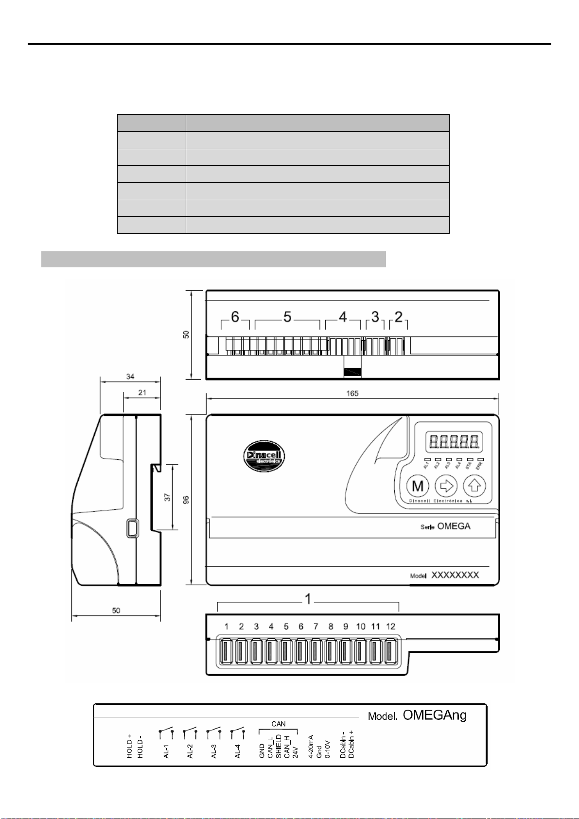
The unit is equipped with a menu by which the individual setting
parameters can be displayed or modified.
a. By Pressing this key for 2 Seconds Enter/exit the menu
b. By Pressing this key inside the menus will navigate through
parameters.
c. Accept and save modified values when modifications are on
progress.
a. During menu navigation: Enter to modify a parameter.
b. While modifying a parameter: Chose digit to change.
a. During menu navigation: Show the stored value of the selected
parameter.
b. While modifying a parameter: Change the blinking digit
incrementally from 0 to 9.
User manual OMEGA
/
NG
4
Note: After two minutes without any operation, the unit automatically returns to the total weight measure
display, independent of the menu item previously selected.
Led Functions
AL1 Full Load Alarm Indicator
AL2 Over Load Alarm Indicator
AL3 Zero Load Level Indicator (Empty Cabin)
AL4 Slack Rope tension indicator
STA Led status ( For CanOpen: Status Led )
ERR Error ( For CanOpen: Error Led)
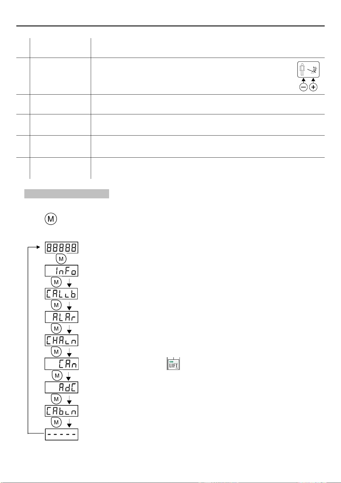
3. DIMENSIONS, INSTALLATION AND CONNECTIONS
User manual OMEGA
/
NG
5
1Sensor inputs Up to 12 USB Connectors for easy plugging
2Cabin display
output
Output It provides two types of output:
INC: Progressive display MB-D (two wire connection without
polarity).
LED: If overload, it will be an intermittent voltage of 5V (max. 30mA)
with the polarity shown in the figure.
3Analog outputs This output reflects the sensors signal over the range 0-10V and
4-20mA. Common signal is GND. (See the ADDITIONAL FUNCTIONS chapter).
4Can Open Input 24 VDC power supply and Can Bus in an Open Style connector
5Relay
connections for
alarms
Terminals of the alarm relays.
(See the alarms section in chapter 8)
6HOLD input This function will be activated if an input voltage from 24 to 230V (DC or AC) is
applied. (See the ADDITIONAL FUNCTIONS chapter).
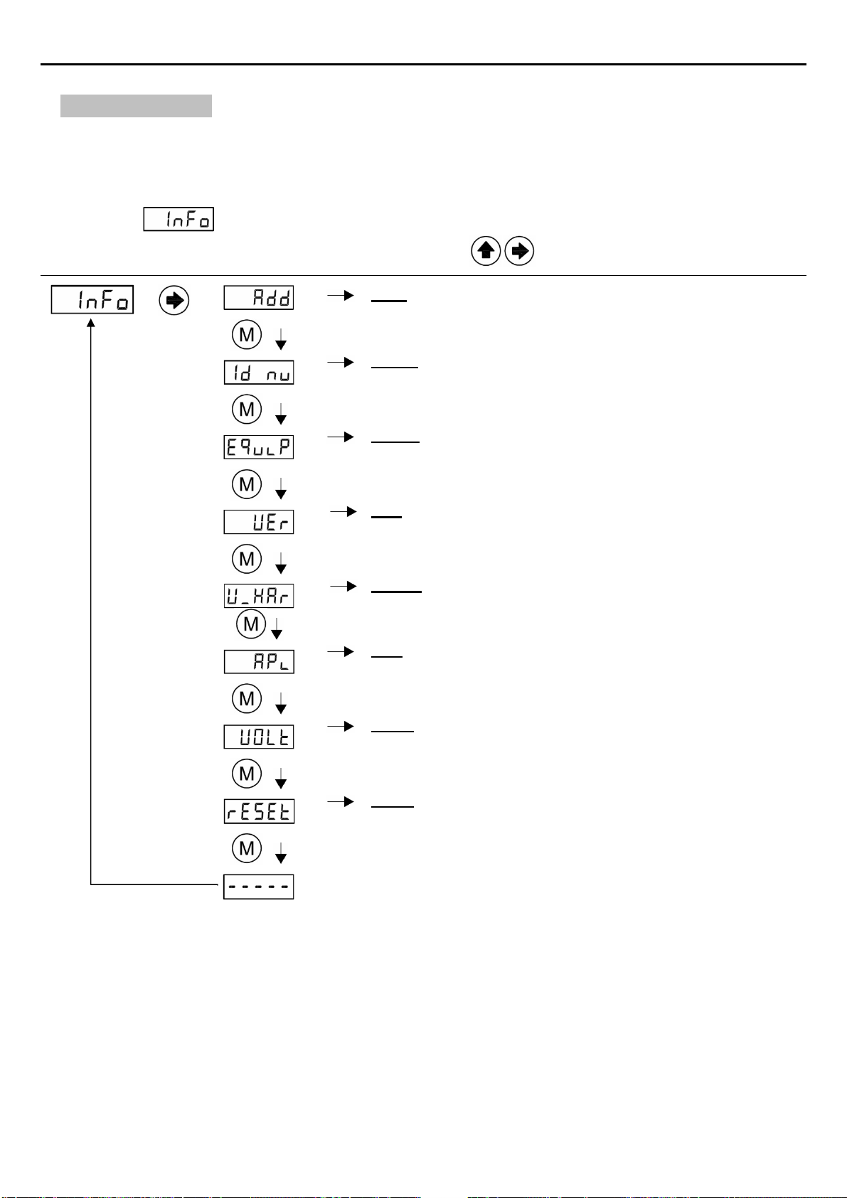
4. MENU STRUCTURE
The menu has the cyclic structure shown in the following figure.
Press button for 2 seconds to enter and then press it repeatedly to move from a parameter to
another. Press it for 2 seconds to exit.
Weight indication. Display the value of the measured load
Press Menu for 2 Seconds
Shows Identification Data of the unit
System calibration. These menus shows all parameters related with the load cell
Configuration.
Alarm Levels configuration.
Chain compensation options
CanOpen Configuration.
(Only relevant for OMEGA-C models )
Load Cell mv/v. signal value.
Led or Cabin Display Output
(Only relevant for OMEGA-4RM models )
Pressing Menu for 2 seconds inside the internal navigation menu will end the menu navigation and
return to Display the value of the measured load

User manual OMEGA
/
NG
6
5. HOW TO VISUALIZE OR CHANGE PARAMETERS
Once inside any menu and displaying the parameter to be viewed or changed:
Press to display the current value.
Press to select the parameter to be modify :
Press to choose the digit position to change ( Flashing )
Press to change the value of the Current Flashing digit position. (if there’s no flashing digit,
change the value with key directly)
Press twice to save the value.
If button is not pressed again before display Flashing ends (10 seconds), the
parameter value will not be changed.
After any of these operations, the display will show the current parameter.
User manual OMEGA
/
NG
7
6. DEVICE INFO
All new NG units store some important information in this menu in order to build wireless
connections with any remote future unit developed by Dinacell Electronica. All parameters can be read in
this submenu.
Submenu
Press to enter Check value Enter to modify
Add: NG Network Address of the unit.
Id_nu: Identification number of the unit. Unique identification
for each unit.
Equip: Model of unit.
Valid Values: OME
Ver: Firmware Version of Unit OMEGANG
Valid Values: 1.00 and above
V_Har: Hardware Version of Unit OMEGANG
APi: ApiVersion of NG Dinacell Network
Valid Values: 100 and above
VOLt: Internal Power supply Voltage of unit OMEGANG
Valid Values: (around 24 volts )
rESE: Reset all parameters value to Factory defaults. All
calibration data will be lost

User manual OMEGA
/
NG
8
7. SYSTEM CONFIGURATION
This section describes how to configure the Unit to obtain the best measure accuracy. The configuration
is done in Menu.
Press
to enter Check value Enter to modify
nSen: Number of sensors connected to ropes or cables. If this
parameter is not set correctly, the unit will show Err1 and
alarm relays will be activated.
Iref: Initial Reference of the sensors. This operation must be
done with the Sensors uninstalled on the ropes.
Note: It is mandatory to do the iref operation if Wire Rope Tension
balancing is going to be adjusted.
If you forget to make this operation or no rope tension equalizing
needs to be performed, you can select the option “rese” on Iref Submenu to
make the iref with sensors installed.
Units: Display Weight units. Available units are Kilos/Pounds
SusPE: Type of suspension at installation:
1:1 2:1 3:1 4:1
Zero: Zero point adjustment With empty elevator. Store a
Countdown value for Zero and load calibrating parameters
Load: Well known weight applied inside the elevator to do the
weight calibration of the unit. (It is recommended to set up to
60% of the nominal load of the elevator.)
Cell: Nominal load cell sensibility. This value is calculated
when LOAD operation is done. User shouldn´t modify this
value. ( If this parameter is modified the previous calibration
settings will be overwritten)
tSen: indication of individual Sensor Rope weights. On the
display appears the weight in units selected (e.g. 100kg)
alternating with the Sensor number ( Se 1)

User manual OMEGA
/
NG
9
Calibration process:
1) Install the control unit with the information of the INSTALL AND CONNECTIONS chapter.
2) Connect Load Cell to the OMEGANG
3) Power up the unit with the correct voltage (see the ELECTRICAL SPECIFICATIONS chapter).
4) Go to Submenu:
5) Detail Calibration Procedure:
Follow next steps to set a precise Load Measuring system
5.1 ) Select number of sensor ropes.
5.2 ) Do and Iref “ALL” Operation with sensors not installed on the ropes.
Note: if your sensors are already installed and you don’t need to equalize the rope tension
you can select “rese” option on Iref submenu.
5.3 ) Select display measuring units. Available units are Kilograms or Pounds
5.4 ) Select Suspension. By default 1:1 is selected
5.5 ) Zero adjustment:
a) Install sensors on the ropes when using SWK, SWR or LCA.
b) Select Submenu Zero by pressing
c) Change countdown value if desire.
d) Press menu and display will start flashing
e) Make sure elevator is empty and confirm operation by pressing again.
f) The countdown will start. During this time, the car weight must not change.
5.6 ) Load Point adjustment: With This function the Unit will be calibrated with the best
accuracy.
Put a well known weight into the cabin. Is recommendable a 60% of elevator duty load.
To make the Load point adjustment:
a) Select Submenu Load by pressing
b) Set the value with the total Load added into the elevator.
c) Press menu and display will start flashing
d) Confirm operation by pressing again.
e) The countdown will start. During this period of time, the car weight must not change
5.5) This parameter stores the Sensor Sensibility. Cell value is automatically calculated after a
Load Point adjustment. If Cell Value is changed, the previous calibrating process will be
overwritten.

User manual OMEGA
/
NG
10
8. ALARMS CONFIGURATION
The alarms values correspond to the load threshold at which each relay change its state.
The relays allows to be configured individually as make or break contact
Alarms are activated when their threshold is exceeded. The Unit OMEGANG has 4 different alarms:
AL-1 (Full Load, Relay #1):
Change of state when exceeding the load programmed in
AL-2 (Over Load, Relay #2):
Change of state when exceeding the load programmed in
AL-3 (Zero Load, Relay #3):
Change of state when falling below the load programmed in
Note: This alarm is active below Alarm3 Threshold.
AL-4 (Rope Tension Difference and Slack Rope Tension, Relay #4):
Change of state if any rope has a slack rope tension or if any rope deviates from the average of all
other ropes at least by the percentage programmed in .
The working procedure of the relays as a make or break contact can be changed for each alarm output
using the parameter. Valid values are (Close) for the operating mode MAKE and (Open)
for the operating mode BREAK.Close is a normally closed relay and OPEn is a normally open
relay. Alarm LEDs indicators will be activated when the display measured value overload corresponding
alarm level
Note:LEDsarenotrelatedtorelaystatebutalarmslevels.
Table of contents
Other dinacell Accessories manuals












