Delta BIESEMEYER 78-955 User manual

INSTRUCTION MANUAL
BIESEMEYER®
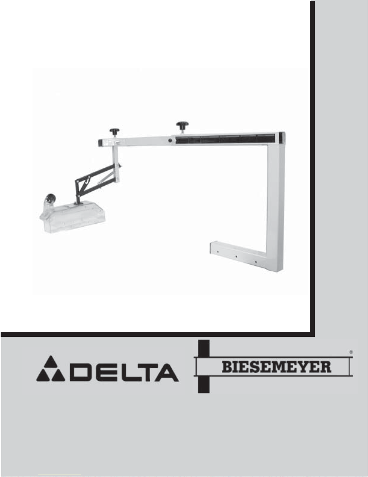
10” TABLE SAW BLADE GUARD SYSTEMS
(MODEL 78-955 FOR 28”, 30” AND 40” T-SQUARE®FENCES)
(MODEL 78-960 FOR 50” AND 52” T-SQUARE®FENCES)
PART NO. 1350436
DATED 06-15-2006
To learn more about DELTA MACHINERY visit our web
site at: www.deltaportercable.com. For Parts, Service,
Warranty or other assistance, please call 1-800-223-7278
To learn more about BIESEMEYER MANUFACTURING
visit our web site at: www.biesemeyer.com. For Parts,
Service, Warranty or other assistance, please call
1-800-782-1831

INTRODUCTION
SAFETY RULES
1. FOR YOUR OWN SAFETY, READ INSTRUCTION
MANUAL BEFORE OPERATING THE BLADE GUARD
SYSTEM. Learn its application and limitations as well as the
specific hazards peculiar to it.
2. ALWAYS WEAR EYE PROTECTION.
3. ALWAYS WEAR SAFETY GLASSES that comply with
ANSI 287.1. Everyday glasses only have impact resistant
lense; they are not safety glasses. Also use face sheild or
dust mask if cutting operation is dusty.
4.KEEP WORKAREACLEAN. Clutteredareasand benches
invite accidents
5. KEEP CHILDRENAND VISITORSAWAY.All children and
visitors should be kept at a safe distance from the work area.
6. USE RECOMMENDED ACCESSORIES. The use of
accessories and attachments not recommended by Delta
may cause hazards or risks of injury to person.
7. TO PREVENT injury from kickback or blade contact, use
blade guard and splitter whenever the cutting operation
permits.
8. ALWAYS use a push stick when cutting narrow stock.
9. ALWAYS stay alert and keep hands out of path of saw
blade.
10. DRUGS, ALCOHOL, MEDICATION. DO NOT operate
blade guard while under the influence of drugs, alcohol, or
any medication.
11. WARNING: The dust generated by certain woods and
wood products can be injurious to your health. ALWAYS
operate machinery in a well ventilated area and provide for
proper dust removal. Use wood dust collection systems
whenever possible.
12. ALWAYS use blade guard, splitter and anti-kickback
fingers for every operation for which it can be used, including
all thru-sawing. Thru-sawing operations are those when the
blade cuts completely through the workpiece as in ripping or
cross-cutting.
13. AVOID awkward operations and hand postions where a
sudden slip could cause your hand to move into the cutting
tool.
14.AVOID KICKBACKS (workthrownbacktowardsyou)by:
A. Keeping blade sharp
B. Keeping rip fence parallel to saw blade
C. Keeping splitter and anti-kickback fingers
and guard in place and operating.
D. Not releasing the work before it is pushed
all the way past the saw blade.
E. Not ripping work that is twisted, warped
or does not have a straight edge to guide
along the fence.
15. PROVIDE adequete support to the rear and sides of the
saw table for wide or long workpieces.
16. NEVER attempt to free a stalled saw blade without first
turning the saw “OFF.”
17. ALWAYS STOP the saw blade before removing scrap
pieces.
18. NEVER perform layout, assembly or set-up work on the
table while the saw is running.
19. DISCONNECT saw from power source before changing
blades or servicing.
20. NEVER usesolventsto clean plastic parts.Solventscould
possibly dissolve or otherwise damage the material. Only a
soft damp cloth should be used to clean plastic parts.
21. SHOULD any part of your blade guard be missing,
damaged, or fail in any way, replace missing, damaged or
failed parts before resuming operation.
22. SAVE THESE INSTRUCTIONS. Refer tothemfrequently
and use them to instruct others.
The BIESEMEYER®T-SQUARE®Blade Guard System is designed for use on most table saws. The table mount is
designed for use on saws equipped with the BIESEMEYER®T-SQUARE®Saw Fence system. The 78-955 and 78-960
are designed for use ONLY on Delta 10” Unisaws, 10” Tilting Arbor Saws and 10” Contractors Saws equipped
with the BIESEMEYER®30” or 50” capacity T-SQUARE®fence system respectively.
OSHA regulations and ANSI standards require that a splitter and anti-kickback device be utilized for through
cutting operations. The 78-955 and 78-960 comply with these regulations.
2

UNPACKING
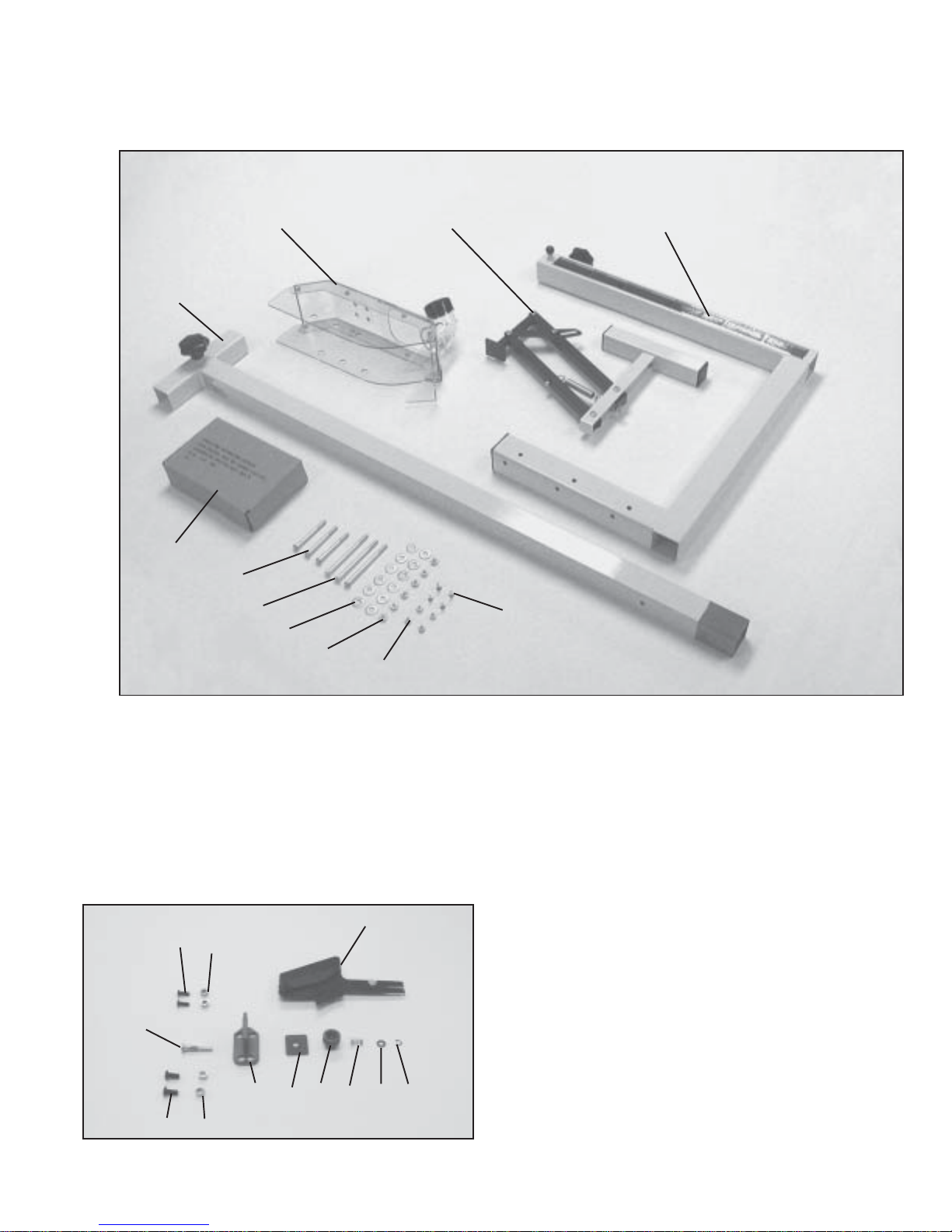
Carefully unpack the blade guard and all loose items from the carton. Figures 1 and 2 illustrate all items supplied
with the Blade Guard System.
1 - Blade Guard Basket Assembly
2 - Basket Body Assembly
3 - Guard Mounting Base
4 - T-Arm
5 - Splitter Assembly (Contents shown in Fig. 2)
6 - 1/4-20 x 2-3/4” long hex head screws (3)
7 - 1/4-20 x 3-3/4” long hex head screws (3)
8 - 1/4” flat washers (12)
9 - 1/4-20 hex nuts (6)
10 - #10-32 Lock Nut (4)
11 - #10-32 x 5/8” Flat HD Screw (4)
3
12 - Splitter
13 - 1/4-20 x 5/8” button head screws (2)
14 - 1/4” bushing (2)
15 - Stud
16 - 5/16-18 x 5/8” button screws (2)
17 - 5/16” bushings (2)
18 - Splitter mounting bracket
19 - Plate
20 - Knob
21 - Spring
22 - 1/4” flat washer
23 - E-ring
Fig. 2

Fig. 1
12
13 14
15
16 17
18 19 20 21 22 23
1
23
4
5
6
78910
11

INSTALLATION
4
Fig. 3
Fig. 4
Fig. 5
Fig. 6
DISCONNECT THE SAW FROM THE POWER SOURCE!
IMPORTANT: The following instructions for
assembling the splitter illustrated in this manual are
shown on a Delta 10” left-tilting arbor Unisaw.
Assembly to a right-tilting arbor saw will be opposite
to what is shown except where noted.
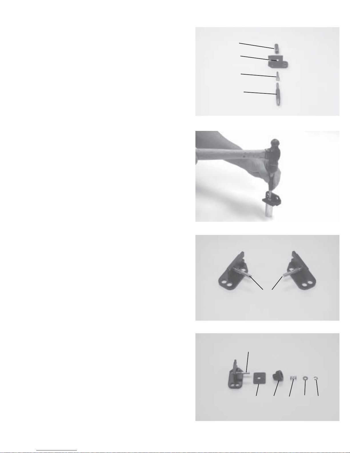
1. Locate the components shown in Fig. 2, for the splitter
assembly.
2. Insert and seat stud (A) Fig. 3 through hole in side of
splitter mounting bracket (B). NOTE: It will be necessary
to have a hammer, punch (C) and a tool with a recessed
hole similar to a deep well socket (D) in order to seat stud
(A) Fig. 3, and used as shown in Fig. 4.
3. Fig. 5 illustrates stud (A) assembled to splitter
mounting bracket for both the left and right tilting arbor
saw.
4. Loosely assemble plate (E) Fig. 6, knob (F), spring (G),
flat washer (H) and E-ring (J) onto stud (A) as shown
assembled in Fig. 7.
A
B
C
LEFT-TILT RIGHT-TILT
D
E F G H J
A
A

5
5. Locate two bushings each, (K) and (L) Fig. 8, two
1/4-20 x 5/8” button head screws (M); two 5/16-18 x 5/8”
button head screws (N ) and splitter mounting bracket
assembly (P). NOTE: Bushings (K) with smaller I.D.
hole and two 1/4 x 5/8” long screws (M) are used when
mounting the splitter to the Delta 10” tilting arbor saw
and the 10” Contractors saw. Bushings (L) Fig. 14,
with the larger I.D. holes and two 5/16-18 x 5/8” long
button head screws (N) are used when mounting the
splitter bracket to a 10” Unisaw.
6. Depending on what saw you are using, insert bushings
(K or L) Fig. 8, into holes (Q) in the splitter mounting
bracket.
7. Remove the saw blade from the saw arbor.
8. Assemble the splitter mounting bracket (P) Fig. 9, to
theinsideofreartrunionusingtwobuttonheadscrews(N)
Figs. 8 and 9, since we are mounting the splitter to a 10”
Left tiltingArbor Unisaw. NOTE: Just snug up button head
screws at this time.
9. Using a straight edge (R) Fig. 10, align the top portion
ofsplittermountingbracket(P)tosawarbor (S) as shown.
Then tighten two screws (N) Fig. 9.
Fig. 7
Fig. 8
Fig. 9
Fig. 10
K
L
M
N
P
Q
Q
NP
R
P
S

Fig. 11
Fig. 12
Fig. 13
Fig. 14
6
10. Insert index pin (T) Fig. 11, through the hole in splitter
(U), as shown, and fasten with locknut (V). Fig 11 illustrates
the index pin assembly arrangement for both right and left
tilting arbor saws.
11. Loosen knob (F) Fig. 12, and slide splitter (U) down as
far as possible into the splitter mounting bracket and tighten
knob (F). Fig 13 illustrates the splitter assembled to the
mounting bracket. IMPORTANT: When performing non
thru-cutting operations, such as dadoing, the splitter (U)
Figs. 12 and 13, can be removed by loosening knob (F).
This enables you to use the guard basket for non
thru-cutting operations.
GUARDASSEMBLY
12. Clamp the guard mounting bracket (A) Fig. 14 to the
back rail (B) of the fence system, making sure the inside of
the vertical post (C), is approximately 1/4” past the end of
rail (B).
13. Using a 9/32” drill bit, drill six holes in the rear rail, three
each to be drilled into the horizontal and vertical portion of
the back rail (B), using the holes (D) and (E) in the mounting
bracket as a template.
T
T
U
V
A
B
C
D
E
F
U
U
F
LEFT-TILT RIGHT-TILT

Fig. 15
Fig. 16
Fig. 17
Fig. 18
7
14. Fasten the mounting bracket (A) Fig. 15, to the back
rail (B) using the three 2-3/4” long hex head screws (F),
three 3-3/4” long hex head screws (G), twelve 1/4” flat
washers and six 1/4-20 hex nuts. Place one flat washer
oneach hexheadscrew beforeinserting throughthe guard
mount bracket. Then place the remaining washers on the
hex head screws and secure with the six 1/4-20 hex nuts.
15. Thread knob (H) Fig. 16, into mounting bracket (A) as
shown. Insert T-arm (J) Fig. 16, into mounting bracket (A).
16. Pull stop pin (K) Fig. 17, to allow the T-Arm to slide
past stop pin indexing hole (L).
17.Assemble basket body assembly (M) Fig. 18, to blade
guard basket assembly (N) using the four (4) #10-32 x
5/8” flat head screws (P) and four (4) #10-32 locknuts (Q).
Do not completely tighten screws at this time.
A
B
F
G
H
A
J
K
L
MN
P
Q

Fig. 19
Fig. 20
Fig. 21
8
18. Make certain the hood assembly (M) Fig. 19, is in line with
the basket body assembly (N). When you are certain hood
assembly (M) is in line with basket body assembly (M), tighten
4 screws (P).
19. Thread locking knobs (R) Fig. 20, into threaded nut on
adjusting arm (J). Insert basket body assembly (N) Fig. 20
into the “T” of the adjusting arm (J).
20. Loosen the two locking knobs (R) & (H) Fig. 21, and adjust
T-arm (J) and blade guard basket assembly (N) until the guard
basket (M) is centered over the saw blade.
M
N
P
J
N
R
RH
J
N
M

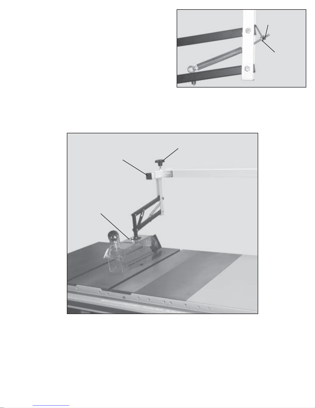
21. IMPORTANT: Make certain the rear end of the guard
basket frame (M) Fig. 22, is 3/8” away from the front of
the splitter (S) and tighten the two locking knobs (R)
and (H) Fig. 21.
22. To raise the guard basket (M) Fig. 23, above the saw
blade, simply lift up the hood by the dust port until guard
catch (T) engages hex head bolt (U) as shown in Fig 24. It
may be necessary to loosen hex head bolt (U) to allow the
guard catch (T) to fall back to engage bolt (U).
NOTICE: DO NOT LIFT THE GUARD BASKET FROMANY
OTHER POINT EXECEPT THE DUST PORT!
23. To lower the guard basket assembly (M) pull forward on
guard catch (T) Figs. 24 & 25.
Fig. 22
9
Fig. 23
Fig. 24
Fig. 25
MT
U
T
M
S
T
M

Fig. 27
10
24. There is an adjustment screw to achieve the desired
weight of the guard basket (M) Fig. 27, on the workpiece.
To make an adjustment, loosen locknut (V) Fig. 26, and
turn wing nut (W) clockwise to decrease the pressure or
counter-clockwise to increase the pressure. After the
desired pressure is achieved, tighten locknut (V).
V
W
25. Front to back movement of the blade guard basket (N) Fig. 27, is obtained by loosening locking knob
(R) and sliding basket body arm (N) in or out as desired.Always tighten locking knob (R) after adjusment
is complete. NOTICE: IT IS RECOMMENED THAT THE BACK OF HOOD ASSEMBLY (M) BE
POSITIONED 3/8” IN FRONT OF THE SPLITTER BLADE.
Fig. 26
M
R
N
This manual suits for next models
1
Table of contents
Other Delta Accessories manuals

Delta
Delta SH-OP01 User manual

Delta
Delta 46-896 User manual

Delta
Delta LE-50637 User manual

Delta
Delta PB-C1001 User manual

Delta
Delta SH-WS02 User manual

Delta
Delta GT-9000 User manual

Delta
Delta AMBIS User manual

Delta
Delta DPA Series User manual

Delta
Delta DVP-EH Series User manual

Delta
Delta PB-C1003 User manual

Delta
Delta 41319 Series User manual

Delta
Delta AS-BF Series User manual

Delta
Delta RetroSign GR1 User manual

Delta
Delta LE-753112 User manual

Delta
Delta CS-01 User manual

Delta
Delta ELEKTRA UV E-5 User manual

Delta
Delta PB-A1002 User manual

Delta
Delta GRX User manual

Delta
Delta InfraSuite RWD030R User manual

Delta
Delta dvp04pt-s User manual