
Dedicated Micros PICKAPOINT User manual

1
Pick-a-Point
User Guide

2
Table of Contents
Overview 3
Notes for User 3
Workstation CPU Screen Layout 4
Menu Bar 4
Map Window 5
Multi-Screens 7
Start/Stop Sequence 8
Set Time/Date 8
DVR Search and Playback 9
Download / Copy Video 10
Event List 12
Observed Events 13
Logging an event 13
Replaying an event 13
Site List 14
Description 14
Manager Menus 15
Setting up Sequences 17
Basic Configuration 18
Connections at the rear of the unit 18
Packing List 19
Logging on 19
3
Overview
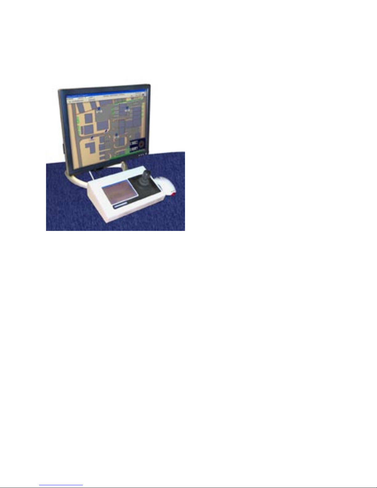
Pick-a-Point is a dedicated IP keyboard solution
with joystick control that is designed to replicate the
traditional analogue matrix, offering digital reliability
and retrieval speed. Integration with existing analogue
systems is seamless, giving the station control over all
servers, domes, DVR’s and cameras.
It can operate as an additional control point on an
existing Pick-a-Point system, or work standalone to
provide composite viewing and control of any Dedicated
Micros NetVu Connected Server, DVR or IP Camera.
The keyboard and joystick control offer a familiar
environment for operators, eliminating the retraining
requirement associated with PC based systems. The
integrated touch screen keyboard provides intuitive
camera selection and joystick telemetry control,
removing the need for a QWERTY keyboard.
The powerful graphical user interface allows quick
navigation of the menus and access to sites. Operators
can simply pick and click cameras to view the required
images. The bespoke system, with customer specific
maps installed, is designed as a turnkey solution to
meet the exact operational requirements.
The system is configured and commissioned on site by a Dedicated Micros technician or appointed individual.
Custom maps are added to suit the users requirements, offering a graphical representation of the sites being
monitored. Camera icons and hotspots included in the map aid the operators, by simplifying camera selection
and system navigation.
Combined with Dedicated Micros’ world leading NetVu Connected technology, the Pick-a-Point system offers a
powerful networked monitoring solution.
More information is available from the Dedicated Micros Website.
Go to
www.dedicatedmicros.co.uk
Notes for User
• Cameras can be selected directly from the map or by selecting the camera number from the Matrix
keyboard.
• The Pick-a-Point system can handle any number of cameras and monitors. Connection is limited by the
practical capability of a single operator to monitor all the connected sites.
• Hover over the camera on the map to see the IP address of the Server.
• Multiscreen option will give a Quad screen display.
• There is built in support for the listed Mouse and CD writer. Before connecting an alternative, please
contact Dedicated Micros’ Technical Service department for advice.

4
Workstation CPU Screen Layout
The workstation screen is divided into two sections pictured below.
The menu bar is displayed across the top of the screen, with the map window below.
Menu Bar
The menu bar at the top of the screen allows access to the available menus. These will change according to
the log in used. The menu bar, shown below, is what a user will have available. A description of each button
function is listed below.
Menu Bar
1 2 3 4 5 6 7 8 9
10 11 12 13

5
User Button Functions
1 Displays the key number selection from the keypad.
2 Displays the currently selected system camera number.
3 Opens the ‘Log Off’ system window (see Logging On and Off).
4 Returns the display to the top level map.
5 Opens the ‘Multi Screen’ window (see Multi-Screens).
6 Starts or stops a sequence on the currently selected monitor (see
Sequences).
7 Allows the operator to set the workstation time and date (see Setting The
Time And Date).
8 Opens the DVR search and playback window (see DVR Search /
Playback).
9 Logs / recalls a time, date and camera number when a suspicious event
occurred (see Observed Events).
10 If an MPEG-4 or MJPEG video source has been selected, there will be an
option to dynamically switch the view between JPEG and MPEG modes.
The button will display the alternative option. The current feed will be
shown on the monitor.
11 Displays a list of sites / map levels (see Site list).
12 Allows the monitor selection to be changed (see Changing monitors).
13 Displays program version information.
Map Window
The map window shows a plan for the site under observation. These maps have been loaded as part of the
initial configuration process by the integrator and give the operator information on the location of the cameras,
to enable efficient and quick tracking and operation.
The icons represent the different cameras that are linked to them. When a camera is selected onscreen, it
will be displayed on the monitor currently under control. Refer to the Tcommand Keyboard manual for more
information on selecting cameras and monitors.
Available icons
Dome Camera Camera Selected Camera

6
Backup Pick-a-Point keyboard
If the connection to the Pick-a-point keyboard is lost, an onscreen version (shown below) will automatically
appear. This can be dragged to any position on the monitor. It will disappear once the connection to the
keyboard has been re-established.
The on-screen keyboard offers telemetry control via the joystick on the right, and the ability to control zoom, iris
and focus.
Logging On and Off
To log off;
1) Touch or click on the ‘Log Off’ button on the menu bar. The Log Off window will appear.
2) Enter the four digit pin code (9999).
3) The ‘Logged Off’ window will be displayed.
To log on;
1) Touch or click on the red area and the ‘Log On’ button on the menu bar.
2) Enter the appropriate four digit PIN code.
7
Multi-Screens
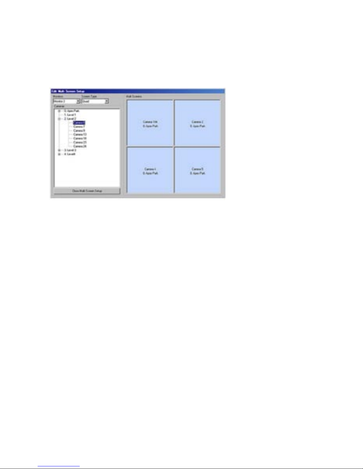
The ‘Multi Screens’ button allows the currently selected monitor to placed into a quad. This enables 4 images
to be displayed on a single monitor.
1) Use the ‘Monitors’ drop down menu to select which monitor will show the multi screen display.
2) Use the drop down menu under ‘Screen Type’ to select the display as quad (4 way) screen.
3) Cameras can now be dragged from the camera list into the viewing frames. Select a camera from the list
in the left window and ‘drag and drop’ into the appropriate frame.
This menu can also be used to assign a camera to a monitor in full screen mode.
1) Use the ‘Monitors’ drop down menu to select which monitor will show the full screen display.
2) Use the drop down menu under ‘Screen Type’ to select the display as Full Screen.
3) Cameras can now be dragged from the camera list into the viewing frame.

8
Start/Stop Sequence
To start a sequence;
1) Select the required monitor (see Changing monitors).
2) Touch or click the ‘Start / Stop Sequence’ button.
The button for the monitor being sequenced will display an ‘S’ next to the monitor number.
3) Touch or click the button again to stop the sequence.
Set Time/Date
To adjust the workstation time and date, click or touch the ‘Set Time / Date’ button on the menu bar. The
window shown below will be displayed.
1) Click on or touch the plus and minus symbols next to the hours, minutes or seconds to adjust the time.
Click ‘Update Time’ to save the changes.
2) Click on the drop down menu next to the date to display the calender. Select the correct date and close
the window. Click ‘Update Date’ to save the changes.
3) Click or touch ‘Close’ to close the window.

9
DVR Search and Playback
This facility is only available when logged in as a supervisor.
To review and download recorded images;
1) Touch or click the camera required for review
2) Touch or click on the ‘DVR search / playback’ button.
The DVR Control window will pop up.
This window will allow an operator to review recorded images from the selected camera, based upon
the time of recording. These can be fast forwarded and fast rewound on screen for easy access.
Use the Time and Date buttons in the right hand window to set the search parameters.
DVR Control
1
Opens the Download / Copy video window (See Download/Copy Video).
2
Switches the camera from playback to live mode.
3
Resumes playback from the time and date entered in the search section.
4 Selects the time of the recorded images for review.
1
13
12
11
10
876
5
4
32
9

10
5 Selects the required recording date for review
6 Begins playback from the selected time and date.
7 Drop down menu sets the playback speed.
8
Launches the playback utility from the DVD after successfully downloading
an incident and writing it to a DVD.
9 Closes the DVR Control window.
10 Event List button opens the list of Events recorded by the DVR. (See Event
List below).
11
Fast forward the playback (Also possible using joystick pan right)
12
Rewind the playback (Also possible using joystick pan left).
13
Pauses the playback.
Download / Copy Video
1
2
3
4
5
6
7
8
9
10
11
Other manuals for PICKAPOINT
2
Table of contents
Other Dedicated Micros Recording Equipment manuals

Dedicated Micros
Dedicated Micros DV-IP HD Operating instructions

Dedicated Micros
Dedicated Micros SD Advanced Operating instructions
Dedicated Micros
Dedicated Micros SD Range Operating instructions

Dedicated Micros
Dedicated Micros Digital Sprite Lite User manual

Dedicated Micros
Dedicated Micros DV-IP Express Instruction Manual
Dedicated Micros
Dedicated Micros PICKAPOINT User manual



