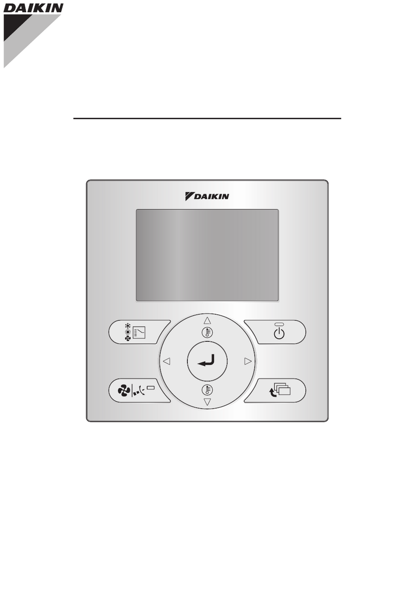
Daikin BRC1E62 User manual

Be sure to read this installation manual
before installing this product.
BRC1E62
WIRED REMOTE
CONTROLLER
INSTALLATION MANUAL

1
Contents
1. Safety Precautions............................................2
2. Accessories .......................................................4
3. Remote controller installation procedure.......4
4. Functions and menu items of
remote controller buttons...............................10
5. Power-on..........................................................12
6. Field settings ...................................................13
7. Test operation method (in the case
of SPLIT system) .............................................16
8. Checking procedure of Malfunction
(Error) History..................................................19
9. Registration method of the
Maintenance Contact ......................................20
10.Conrmationofregistereddetails .................21
11. Clock & Calendar.............................................22
12. Language..........................................................23
13. Prohibit buttons...............................................24
14. Prohibit Function.............................................25

2
1. Safety Precautions
Also refer to installation manual attached to the indoor unit.
Please read these "Safety Precautions" carefully before installing the remote controller.
● This manual classies the precautions into WARNINGS and CAUTIONS.
Be sure to follow all the precautions below: They are all important for ensuring safety.
WARNING Indicates a potentially hazardous situation which, if not avoided, could
result in death or serious injury.
CAUTION Indicates a potentially hazardous situation which, if not avoided, may
result in minor or moderate injury.
It may also be used to alert against unsafe practices.
● After completing installation, conduct a test operation to check for faults and explain to the customer
how to operate the remote controller and cleaning of it with the aid of the operation manual. Ask the
customer to store the installation manual along with the operation manual for future reference.
WARNING
Ask your dealer or qualied personnel to carry out installation work.
Do not attempt to install the remote controller yourself.
Improper installation may result in electric shocks or a re.
Consult your local dealer regarding relocation and reinstallation of the remote controller.
Improper installation may result in electric shocks or a re.
Install the remote controller in accordance with the instructions in this installation manual.
Improper installation may result in electric shocks or a re.
Be sure to use only the specied accessories and parts for installation work.
Failure to use the specied parts may result in the remote controller falling down, electric shocks or a
re.
Install the remote controller on a foundation that can withstand its mass.
Insufcient strength may result in the remote controller falling down and causing injury.
Make certain that all electrical work is carried out by qualied personnel according to the applicable
legislation (note 1) and this installation manual, using a separate circuit.
In addition, even if the wiring is short, make sure to use a wiring that has sufcient length and never
connect additional wiring to make the length sufcient.
Insufcient capacity of the power supply circuit or improper electrical construction may lead to
electric shocks or a re.
(note 1) applicable legislation means “All international, national and local directives, laws, regulations
and/or codes which are relevant and applicable for a certain product or domain”.
Turn off the power before performing installation work.
Touch with live parts may cause electric shocks.
Do not disassembly, reconstruct or repair.
Electric shock or a re may cause.
Make sure that all wiring is secured, using the specied wirings and ensuring that external forces do
not act on the terminal connections or wirings.
Improper connections or xing may cause an overheat or a re.
The choice of materials and installations must comply with the applicable national and international
standards.

3
CAUTION
To avoid electric shocks due to entry of water or insects, ll the wiring through hole with putty.
Do not operate with wet hands to avoid electric shocks.
Do not wash the remote controller with water.
It may result in electric shocks or a re.
Install the air conditioner, power supply wiring, remote controller wiring and transmission wiring at
least 1 meter away from televisions or radios to prevent image interference or noise.
(Depending on the radio waves, a distance of 1 meter may not be sufcient to eliminate the noise.)
Do not install the remote controller in the following locations:
1. Where there is oil mist, oil spray or vapour for example a kitchen.
Resin parts may deteriorate and fall off.
2. Where corrosive gas, such as sulfurous acid gas, is produced.
3. Where there is machinery which emits electromagnetic waves.
Electromagnetic waves may disturb the control system, and cause a malfunction of the
equipment.
4. Where ammable gas may leak, where there is carbon bre or ignitable dust suspensions in
the air, or where volatile ammables such as thinner or gasoline are handled.
Operating the unit in such conditions may result in a re.
5. High temperature area or directly amed point.
It may cause an overheat or a re.
6. Moist area, or place where may be exposed to water.
If water enters inside of the remote controller, electrical components may fail.
It may result in electric shocks or a re.
When remote controller’s thermostat sensor is used, select the installation location considering the
followings.
● A place where average temperature in the room can be detected.
● A place where is not exposed to direct sunlight.
● A place where is far apart from heat source.
● A place where is not affected by outdoor air due to door opening/closing or the like.

4
2. Accessories
The following accessories are included.
Wood screw Small screw Clamp
Operation
manual Installation
manual Wiring retainer
(M3.5×16) (M4×16)
(2 pcs.) (2 pcs.) (1 pc.) (1 pc.) (1 pc.) (1 pc.)
3. Remote controller installation procedure
3-1 Determine where to install the remote controller.
Make sure to follow " 1. Safety Precautions" when determining the location.
3-2 Make a wiring through hole on the wall if the wires are taken
out from the back side.
Set the center of the wall hole
to the center of the wiring
through hole on the controller
lower case when making the
hole.
Ø8-10
External view of the remote controller
Through
hole
Ø8-10
Lower case
through hole
48.5
40
3-3 Remove upper case.
Insert a screwdriver in the recess of lower case to remove the upper case (2 points).
Upper case
Lower case
Screwdriver
Insert and twist the screwdriver
lightly for removal.
Remote controller Printed Circuit
Board is installed on the upper case.
Take care not to damage the Printed
Circuit Board with the screwdriver.
Take care that dust or moisture does
not touch the Printed Circuit Board.
If the hole size is too large or the location is not
proper, the hole may come out from the controller.
CAUTION

5
3-4 Determine the direction of controller wiring outlet (back
outlet, left outlet, top left outlet, top center outlet).
3-4-1 Back outlet 3-4-2 Left outlet
Cut off resin area (hatched area). Cut off thin area (hatched area) with nippers
or the like, and then remove burr with a le or
the like.
3-4-3 Top left outlet 3-4-4 Top center outlet
Cut off thin area (hatched area) with nippers
or the like, and then remove burr with a le or
the like.
Cut off thin area (hatched area) with nippers
or the like, and then remove burr with a le or
the like.
3-5 Conduct wiring.
1. Switch box and transmission wiring are not attached.
2. Do not directly touch the Printed Circuit Board.
CAUTION
Wiring Specications
Wiring Type Sheathed vinyl cord or cable (2 cores) (*1)
Wiring Size 0.75~1.25 mm2
Wiring Length Max. 500m (*2)
*1. Some countries may require a shielded wiring.
Refer to Installation manual attached to the indoor unit.
*2. This will be the total extended length in the system when doing group control.

6
Prepare the wiring for connection to the remote controller following these instructions.
Peel the insulator and sheath
Cutting guideline
of the wiring
Approx.10 mm
For easy wiring, it is better to
keep approx.10 mm difference
between the length of 2 wires.
Sheath stripping length:
● Approx.150 mm for top left outlet
● Approx.200 mm for top center outlet
Connect the terminals (P/P1, N/P2) of the remote controller to the terminals (P1, P2) of the indoor
unit. (P1 and P2 have no polarities.)
3-5-1 Back outlet
<Wiring fixing guideline>
Lower case
P1
Indoor unit
P2
Upper case
Clamp
Wiring fixing
point
Printed Circuit
Board
Cross-section -
Secure the wiring at
the wiring fixing point
by using attached
clamp.
Clamp

7
3-5-2 Left outlet
Lower case
Upper case
Indoor unit
P1P2
Printed Circuit
Board
3-5-3 Top left outlet
As shown to the left,
install wiring
retainer in order to
prevent wiring
pinching.
Indoor unit
Wiring retainer
Wiring retainer
Upper case
Lower case
Upper case
Wiring
Cross-section -
P1P2
Printed Circuit
Board
3-5-4 Top center outlet
Indoor unit
Wiring retainer
Upper case
Lower case
P1P2
Printed Circuit
Board

8
● Perform the wiring apart from a power line not to receive electrical noise (external noise).
● Seal the wiring outlet hole securely with putty (eld supply) to prevent entry of insects or
the like.
CAUTION
3-6 Fixing procedure of lower case.
In case of wiring a remote controller through top center outlet or back outlet, perform wiring
through the outlet hole in the lower case before it is wall install.
3-6-1 In the case of installation on the wall
Secure by using attached wood screws (2 pcs.).
Wood screws
(M3.5×16)
3-6-2 In the case of installation on the switch box
Secure by using attached small screws (2 pcs.).
Small screws (M4×16)
Switch box
(field supply)
(Use optional accessory
KJB211A)
Switch box for 2 units
(with no cover)
84
46
(Installation pitch)

9
Switch box
(field supply)
(Use optional accessory
KJB111A)
Small screws (M4×16)
Switch box for 1 unit
(with no cover)
84
28
(Installation pitch)
● Select at place for installation face as possible.
● And, do not tighten the installation screws too much not to deform the lower case.
CAUTION
3-7 Install the upper case as original condition.
● Align the upper case with tabs of the lower case (6 points), inset and install the upper case.
● Install the wiring with care to prevent pinching.
● Peel off a protective seal which is attached on the upper case.
Other manuals for BRC1E62
4
Table of contents
Other Daikin Remote Control manuals

Daikin
Daikin BRC1E73 User manual

Daikin
Daikin BRC7E818 User manual

Daikin
Daikin BRC1D619 User manual

Daikin
Daikin BRC1E62 User manual

Daikin
Daikin BRC1D71 User manual

Daikin
Daikin BRC301B61 User manual

Daikin
Daikin DCS302C71 User manual

Daikin
Daikin BRC4C61 User manual

Daikin
Daikin BRC7CB58 User manual

Daikin
Daikin BRC7C510W User manual

Daikin
Daikin BRC1E71 User manual

Daikin
Daikin OM-GS02-02110 User manual

Daikin
Daikin BRC1H71W User manual

Daikin
Daikin BRC1E72 User manual

Daikin
Daikin BRC7EA63W User manual

Daikin
Daikin BRC7EA629 User manual

Daikin
Daikin WRC-COA User manual

Daikin
Daikin BRC1H519K7 User guide

Daikin
Daikin BRC7EA628 User manual

Daikin
Daikin BRC1C71 Dimension Guide