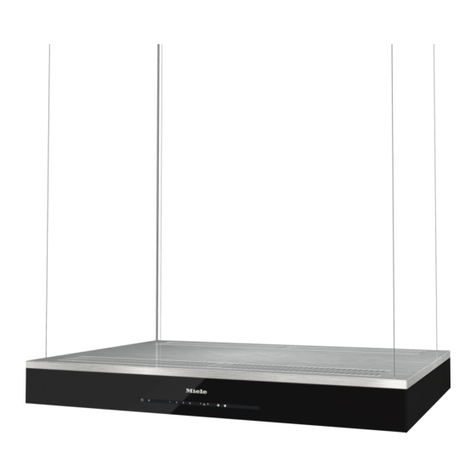
Creda C60AHBG User manual

1
USER
MANUAL
60CM DECORATIVE COOKER
HOOD
V 1.0
MODEL/S
C60AHBG

2
USER
MANUAL
You’ll soon be enjoying your new Creda
Cooker Hood!
It all begins here, with your instructions. Don’t worry, there’s nothing too technical
coming up. Just simple, step-by-step guidance to get you up and running quickly. Sound
good? Then let’s get started.
Help and Guidance
We’re here to help you get the most from your appliance.
Should you require any guidance, a simple solution can often be found online at:
www.creda.co.uk
If you still require further assistance, call one of our experts on 01759 487836.
If you require any technical guidance or find that your product is not operating as intended, a simple solution can
often be found in the Troubleshooting section of these instructions, or online at www.creda.co.uk If you still require
further assistance, call one of our experts on 01759 487836.

3
USER
MANUAL
Contents
PAGE
4
5
6
7
8
11
12
14
15
—
Safety instructions
General View
Accessories
Installation
Mounting Instructions
Control Panel
Maintenance and cleaning
Troubleshooting
Help and Assistance

4
USER
MANUAL
SAFETY INSTRUCTIONS
•IMPORTANT SAFETY INSTRUCTIONS READ CAREFULLY AND KEEP FOR
FUTURE REFERENCE
•It is recommended that the product be installed by authorized persons. Installation by unauthorized persons
could lead to poor operation performance, damage to the product, and accidents. The product will not be
covered by the warranty.
•Avoid connecting a chimney or air duct used to exhaust smoke from appliances that use gas from an electric
cooker hood or other fuels (stove, boiler, thermosiphon, etc.). This warning does not apply to uses without flue.
•Comply with the regulations of the authorities on the discharge of outlet air. (not applicable for devices that
discharge air back into the room).
•When the cooker hood is placed on a gas burning device, the distance between the hob and the hood should
be at least 65 cm. If a larger distance is specified in the installation instructions of the gas burning hobs, this
value should be taken into account.
•While the hood is running, ensure fresh air can enter the environment; especially when used at the same time
with gas baking ovens and solid and gas-fired appliances.
•For your safety, use ”Max 6.A” fuses in the hood installation.
•Do not leave boiling oil on the stove. Pots that contain boiling oil may catch fire by itself.
•Do not operate the hood without using cook wares. High heat may cause some parts of your product to deform
and cause fire.
•The packages pose a danger to children. Never allow children to play with packaging materials. Keep
packaging materials out of reach of children.
•Clean the oil trap aluminum filters regularly. Filters pose risk of fire due to accumulated grease deposits on
them.
•Do not operate your product without filter, and do not remove the filters when the product is in operation. Do
not use non-fire-resistant filtering materials instead of the filter.
•Flammable foods must not be cooked under the appliance.
•In case of any fire, de-energize the device. Cover the flames with a damp cloth or towel. Never use water to put
out the flames.
•Failure to comply with deadlines and periodic instructions may result in a fire hazard.
•This device should not be used by children, persons with physical, sensory or mental abilities, persons lacking
experience or technical knowledge. Do not allow the persons and children under custody to use the product,
play with the product, to perform maintenance and cleaning on the product.
•Kitchen hoods are designed for domestic use. They should not be used for other purposes. May cause various
accidents if used, the device is out of warranty
•The electrical connection of the product must be done to a grounded outlet.
•The electrical connection should only be made once the installation of the appliance has been completed.
•Before the installation, maintenance and cleaning of the product, de-energize the device. (Unplug the device or
turn off the fuse).
•It is forbidden to install the power cord near equipment or materials that may come into contact with heat and
cause distortion. This may cause fire.
•Avoid touching the lamps in your product when they are operating for a long period of time. Since they would
be hot, they could burn your hand.
•Accessible sections may be hot when used with cooking appliances.
•Failure to install screws or fixing installations in accordance with these instructions may result in electrical
hazards.
•Your device is manufactured in accordance with 220-240 V 50 Hz AC AC power supply and requires a fuse of
16 Amp. Should your electrical system differ from these specified values, contact a licensed electrician or your
authorized service center.

5
USER
MANUAL
GENERAL VIEW
Note: Product images are representative. Product may vary in size and model.

6
USER
MANUAL
ACCESSORRIES

7
USER
MANUAL
INSTALLATION
Mounting Distances
Distance between the cooker and the cooker hood must be considered prior to assembly. The distance between
the cooker and the cooker hood should be at least 65 cm.

8
USER
MANUAL
Mounting Instructions
Attach the mounting template to the wall at the distance (65 cm) shown in Figure 1. Drill through points Aand C
with Ø8 mm drill bit. At the Bpoints, drill the chimney mounting plate with a Ø6 mm drill bit, considering the
distance to the ceiling and the maximum length of the flue.
Attach Ø8 mm dowel (5) to points Aand C. Attach Ø6 mm (8) anchors to the Bpoints. Tighten the Ø5 x 50 mm
screw (6) to the Apoints so that the distance between it and the wall is 5 mm. Attach the product body to the
screws at point A and tighten the screws completely. Open the product cover and remove the filters. Complete the
body assembly by mounting Ø5 x 50 mm screws to the Cpoints (6).
Note: The suspension plate mounting shown in detail is optional. It varies based on model.

9
USER
MANUAL
Carbon Filter Assembly
Open the product cover and take out the aluminum filter. (see figure 3) Turn the carbon filter in the direction of the
arrow by pressing the sides. (see Fig. 4)
Flap Assembly
Attach flap tabs to points A as shown in Figure 5. Complete the assembly process so that the nails remain on the
upper surface as shown in Figure 6.
Adapter Mounting
Motor outlet diameter is 150 mm. If a connection with a 120 mm spiral hose be required, the plastic adapter must
be mounted on the body as shown in the figure.
Carbon
Filter
Flap
plastic
Figure 6
Figure 5
Figure 8
Figure 7
150 / 120mm
adapter
Body

10
USER
MANUAL
Flue Installation
Fix the outer flue to the body from point Awith Ø3.5 x 9.5 mm screw. Insert the inner flue into the outer flue and fix
it at the Bpoints with Ø3.5 x 9.5 mm screws.
Air Outlet Connection
Air discharge can be done by flue connection (air discharge to the external environment) or by filtering the air back
to the environment (carbon filter).
Flue Connected Use
For flue-connected use, Ø150 mm or Ø120 mm spiral pipe and clamp must be provided from an authorized service
or service recommended point.
Note: It is recommended to make a pipe connection of Ø150 mm.
The absorbed air is delivered to a flue or outdoor environment with the help of a pipe attached
to the blower motor outlet of the hood in use with flue connection.
WARNING: These parts are not included in the product content and must be purchased.
WARNING: In case of installation connected to a chimney, it is necessary to note all relevant warnings in the
safety and environmental instructions.
Table of contents
Other Creda Ventilation Hood manuals