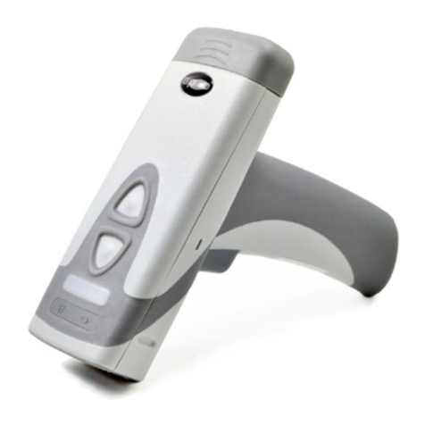
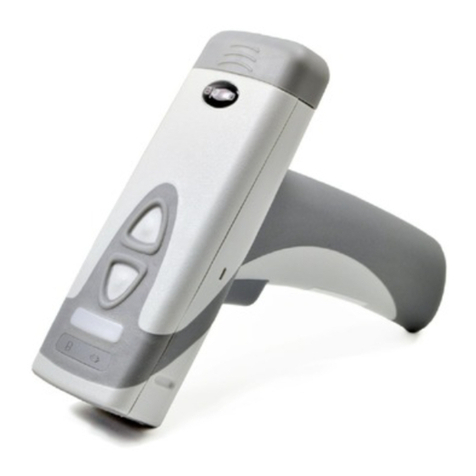
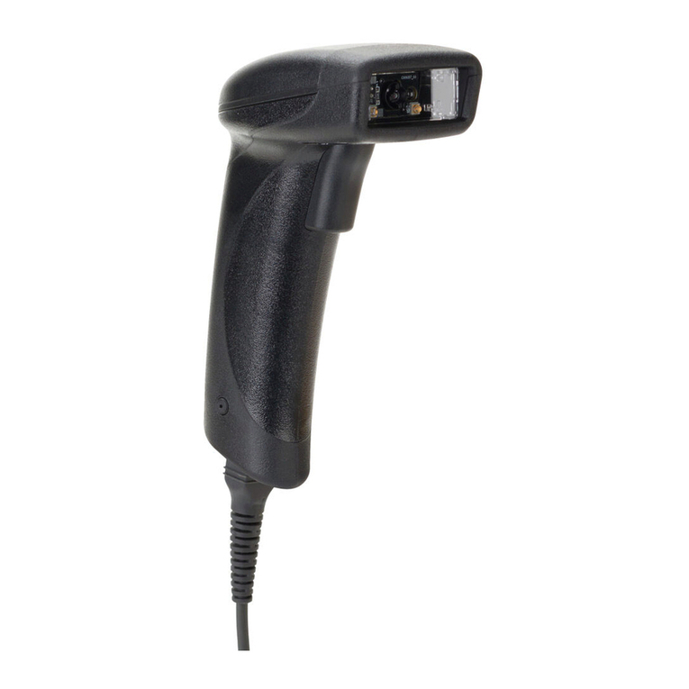
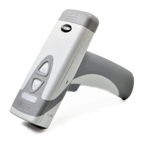
Code Code Reader 822 Series Quick setup guide

CR822x Single Board
Decoded Scan Engine
INTEGRATION GUIDE
Configuration Guidewww.codecorp.com YouTube.com/codecorporation
MANUAL VERSION 08
RELEASE DATE: JANUARY 2018
[.81]
20.50
MOLEX 501745-0301
PIN 1 (TO SCAN ENGINE)
GND
TX
RX
ISP
HIROSE FH33-12S-0.5SH(10)
*Dimension will change based on focus.
Decrease for far focus; increase for near focus.
1
2
4
[.71]
18.00
[.37]
9.40
[.47]
11.90
[.81]
20.50
[.51]
12.83
[.65]
16.46*
[.03]
0.80
[.07]
1.70
[.47]
11.90
[.15]
3.73
PIN 1
[.05]
1.25
[.05]
1.25
BACK VIEW SIDE VIEW
SIDE VIEW
FRONT VIEW TOP VIEW
FRONT VIEW
2X 1.20 [.05]
NON-PLATED
THROUGH HOLES 4X 1.65[.06]
3.00[.12]

2
D026227_08 CR822x Single Board Decoded Scan Engine Integration Guide
Code Reader™822x Single Board Decoded Scan Engine Integration Guide
Copyright © 2016-2018 Code Corporation.
All Rights Reserved.
The software described in this manual may only be used in accordance with the terms of its license agreement.
No part of this publication may be reproduced in any form or by any means without written permission from Code Corporation. This includes electronic or
mechanical means such as photocopying or recording in information storage and retrieval systems.
NO WARRANTY. This technical documentation is provided AS-IS. Further, the documentation does not represent a commitment on the part of Code
Corporation. Code Corporation does not warrant that it is accurate, complete or error free. Any use of the technical documentation is at the risk of the
user. Code Corporation reserves the right to make changes in specifications and other information contained in this document without prior notice, and
the reader should in all cases consult Code Corporation to determine whether any such changes have been made. Code Corporation shall not be liable for
technical or editorial errors or omissions contained herein; nor for incidental or consequential damages resulting from the furnishing, performance, or
use of this material. Code Corporation does not assume any product liability arising out of or in connection with the application or use of any product
or application described herein.
NO LICENSE. No license is granted, either by implication, estoppel, or otherwise under any intellectual property rights of Code Corporation. Any use of
hardware, software and/or technology of Code Corporation is governed by its own agreement.
The following are trademarks or registered trademarks of Code Corporation:
CodeXML®, Maker, QuickMaker, CodeXML® Maker, CodeXML® Maker Pro, CodeXML® Router, CodeXML® Client SDK, CodeXML® Filter, HyperPage,
CodeTrack, GoCard, GoWeb, ShortCode, GoCode®, Code Router, QuickConnect Code, Rule Runner®, Cortex, CortexRM, CortexMobile, Code, Code Reader,
CortexAG, Cortex Studio, CortexTools, Affinity®, and CortexDecoder.
All other product names mentioned in this manual may be trademarks of their respective companies and are hereby acknowledged.
The software and/or products of Code Corporation include inventions that are patented or that are the subject of patents pending. U.S. Patents:
6997387, 6957769, 7428981, 6619547, 6736320, 7392933, 7014113, 7240831, 7353999, 7519239, 7204417, 6942152, 7070091,
7097099, 7621453.
The Code reader software is based in part on the work of the Independent JPEG Group.
Code Corporation, 12393 S. Gateway Park Place, Suite 600, Draper UT 84020
www.codecorp.com

3
D026227_08 CR822x Single Board Decoded Scan Engine Integration Guide
Table of Contents
1 – CR822x Introduction........................................................... 4
1.1 – Product Overview ..................................................... 4
1.2 – SKU Descriptions..................................................... 4
2 – Mechanical Specifications ................................................... 5
2.1 – Decoded Scan Engine Components............................ 5
2.2 – Imager without Mounting Tab Components ................. 5
2.3 – Imager with Mounting Tab Components...................... 5
2.4 – Imager without Mounting Tab
Mechanical Specifications......................................... 6
2.5 – Imager with Mounting Tab
Mechanical Specifications......................................... 7
2.6 – Decode PCB Mechanical Specifications...................... 8
2.7 – Decoded Scan Engine Specifications.......................... 9
2.8 – Enclosure Specifications........................................... 9
3 – Optical Considerations......................................................... 10
3.1 – Window Requirements .............................................. 10
3.2 – Imager Field of View................................................. 11
4 – Electrical Specifications ...................................................... 12
4.1 – System Requirements............................................... 12
4.2 – Electrical System Block Diagram ............................... 12
4.3 – Host Interface Pinouts (CR8222 RS232) ................... 13
4.4 – Host Interface Pinouts (CR8221 USB)....................... 13
4.5 – Electrical Control Signals.......................................... 14
4.6 – Power Modes ........................................................... 14
4.7 – Power On (Boot) Timing Diagram ............................... 15
4.8 – Power Down Timing Diagram ..................................... 16
4.9 – Sleep to Wakeup Timing Diagram............................... 16
4.10 – Image Capture Timing Diagram................................ 17
4.11 – Ribbon Cable Diagram (Decode Board
to Host Interface .................................................... 17
4.12 – Electrical Characteristics (DC)
Absolute Ratings (Min and Max) .............................. 18
4.13 – Electrical Characteristics (DC)
Operating Conditions .............................................. 18
4.14 – Decode PCB to Imager PCB Connector...................... 19
5 – General Specifications ......................................................... 20
6 – Reading Range Specifications .............................................. 21
7 – Warranty ............................................................................ 22
8 – APPENDIX A: CR8000 Development Kit User Guide............... 23
8.1 – Development Board .................................................. 23
8.2 – Development Board Connections ............................... 24
8.3 – Development Board Jumpers ..................................... 25
8.4 – Development Board Fuses......................................... 26
9 – APPENDIX B: CR8200 Development Board ........................... 27
9.1 – Interface ................................................................. 28
9.2 – Power System .......................................................... 29
9.3 – Power Measurements................................................ 30
9.4 – Trigger/Wake Up Switches ......................................... 31
9.5 – Indicators................................................................ 31
9.6 – Development Board Jumpers ..................................... 32

4
D026227_08 CR822x Single Board Decoded Scan Engine Integration Guide
1.2 – SKU Descriptions
The Code Reader™ 822x (CR822x) is a patented, high performance,
miniature barcode imaging engine. The CR822x is the smallest
fully-decoded engine on the market, powered by Code’s proprietary
microprocessing platform, which delivers high-speed barcode reading at
a low power point. The CR822x supports RS232 and USB interfaces for
flexible integration into a variety of devices.
Applications for the CR822x include Medical Devices, ATMs, Price-
Lookup, Lottery, Age Verification, Direct Part Marking, Point of Sale,
Self-Service Kiosks and more.
1.1 – Product Overview
1 – CR822x Introduction
The following table describes the options available for the CR822x
engine. Any SKU (Part Number) can be built using the following table:
SKU: CR822# - S#### - MT# - D## - C###
EXAMPLE: CR822x USB with Standard Focus, Tabs,
No Flex, 2.0” Ribbon Cable.
SKU = CR8221-S0100-MT1-DX-C800
Note: Additional Ribbon Cables, Flex Cables, and Focus options may
be available for your application. Please contact your Code representative
to discuss.
CR822# S#### MT# D## C###
Communications
Interface
Wide Field/High
Density Field Focus Mounting Options Flex Cable Ribbon Cable
1 = Single Board USB
(Ribbon Cable)
0100 = Single Field Optics,
Standard Focus
X = No Tabs X = No Flex Cable X = No Ribbon Cable
2 = Single Board
RS232 (Ribbon Cable)
1= With Tabs 800 = 2.0” Ribbon Cable
801 = 6.0” Ribbon Cable
802 = 12.0” Ribbon Cable

5
D026227_08 CR822x Single Board Decoded Scan Engine Integration Guide
2.1 – Decoded Scan Engine Components
2 - Mechanical Specifications
The CR822x can be ordered with or without scan engine mounting tabs.
1. Imager
2. Spacers
3. Decode Board
4. Screws
2.2 – Imager without Mounting Tab Components
2.3 – Imager with Mounting Tab Components
1. Blue LED Targeting Lens
2. Red LED Illumination Lens
3. Lens
4. Self-Tapping Screw Holes
5. a) Illumination Board; b)Imager Board
6. Connector, Receptacle, 30 pin,
0.4 mm pitch
4
3
5a
2
5b
2
4
6
1
1. Blue LED Targeting Lens
2. Red LED Illumination Lens
3. Lens
4. Self-Tapping Screw Holes
5. a) Illumination Board; b)Imager Board
6. Connector, Receptacle, 30 pin,
0.4 mm pitch
7. Mounting Tabs 4
3
5a
2
2
1
5b
4
6
7
7
7
[.81]
20.50
MOLEX 501745-0301
PIN 1 (TO SCAN ENGINE)
GND
TX
RX
ISP
HIROSE FH33-12S-0.5SH(10)
*Dimension will change based on focus.
Decrease for far focus; increase for near focus.
1
2
3
4
[.71]
18.00
[.37]
9.40
[.47]
11.90
[.81]
20.50
[.51]
12.83
[.65]
16.46*
[.03]
0.80
[.07]
1.70
[.47]
11.90
[.15]
3.73
PIN 1
[.05]
1.25
[.05]
1.25
BACK VIEW SIDE VIEW
SIDE VIEW
FRONT VIEW TOP VIEW
FRONT VIEW
2X 1.20 [.05]
NON-PLATED
THROUGH HOLES 4X 1.65[.06]
3.00[.12]

6
D026227_08 CR822x Single Board Decoded Scan Engine Integration Guide
2.4 – Imager without Mounting Tab Mechanical Specifications
1. The Imager without mounting tabs has
four blind holes (two on top and two on
bottom) available for mounting with self-
tapping screws.
2. Please use #1-32 Trilobular®thread
forming screw or M1.8 Delta PT®
thread forming screw, with the following
dimensions:
Minimum Maximum
Thread Engagement 2.00 mm [.079”] 2.50 mm [.098”]
Length (B) Mounting Substrate
Thickness (A) + 2.00 mm
Mounting Substrate
Thickness (A) + 2.50 mm
Torque N/A 1.5 Ibf-in
[.807]
20.50
FRONT VIEW
[.536]
13.63*
SIDE VIEW
[.138]
3.50
[.512]
13.00
A
Ø1.65 [.065] 3.00 [.118]
4 BLIND HOLES PROVIDED
FOR MOUNTING WITH
SELF-TAPPING SCREWS
TOP VIEW
[.469]
11.90
PIN 1
MOLEX CONNECTOR
P/N: 51338-0374
BACK VIEW
UNITS = MM [INCHES]
*Dimension will change based on focus.
Decrease for far focus; increase for near focus.
2.50 MAX
2.00 MIN
(3.00)
A
B
(Ø1.65)
(Ø2.00)#1-32 OR
M1.8 SCREW
MOUNTING
SUBSTRATE
C8200
HOUSING
*Dimension will channge based on focus.
Decrease for far focus; increase for near focus.
UNITS = MM[INCHES]

7
D026227_08 CR822x Single Board Decoded Scan Engine Integration Guide
2.5 – Imager with Mounting Tab Mechanical Specifications
1. In addition to the four blind holes (two
on top and two on bottom) available
for mounting with self-tapping screws,
the Imager with mounting tabs has two
2.50mm [.098”] clearance holes.
2. Please use #1-32 Trilobular®thread forming
screw or M1.8 Delta PT®thread forming
screw, with the following dimensions:
Minimum Maximum
Thread Engagement 2.00 mm [.079”] 2.50 mm [.098”]
Length (B) Mounting Substrate
Thickness (A) + 2.00 mm
Mounting Substrate
Thickness (A) + 2.50 mm
Torque N/A 1.5 Ibf-in
4X Ø1.65
[.065]
3.00
[.118]
2X Ø2.50 [.098]
[.039]
1.00
[.196]
4.99
[.469]
11.90
[.138]
3.50
UNITS = MM [INCHES]
*Dimension will change based on focus.
Decrease for far focus; increase for near focus.
2.50 MAX
2.00 MIN
(3.00)
A
B
(Ø1.65)
(Ø2.00)#1-32 OR
M1.8 SCREW
MOUNTING
SUBSTRATE
C8200
HOUSING
[1.024]
26.00
[.512]
13.00
[.536]
13.63*
[1.244]
31.60
A
PIN 1
FRONT VIEW SIDE VIEW
TOP VIEW
BACK VIEW
MOLEX CONNECTOR
P/N: 51338-0374

8
D026227_08 CR822x Single Board Decoded Scan Engine Integration Guide
2.6 – Decode PCB Mechanical Specifications
DC822x
The DC822x mounts to the back of the CR8200 imager.
UNITS = MM[INCHES]
KEEP OUT (2.20 [.087] HIGH)
2X 3.00
[.118]
2X 1.70
[.067]
2X 0.95
[.037]
2X 2.25
[.089]
1.20
[.047]
2.25
[.089] 2.00
[.079]
TOP BOTTOM
2.00
[.079] .80
[.031]
KEEP OUT (1.50 [.059] HIGH)
20.50
[.807]
MOLEX 501745-0301
PIN 1 (TO SCAN ENGINE)
0.80
[.031]
1.70
[.067]
11.90
[.469]
3.73
[.147]
GND
TX
RX
ISP
HIROSE FH33-12S-0.5SH(10)
18.00
[.709]
9.40
[.370]
PIN 1
1.25
[.049]
1.25
[.049]
2X 1.20 [.047]
NON-PLATED THROUGH HOLES
FRONT VIEW SIDE VIEW
BACK VIEW
TOP VIEW BOTTOM VIEW

9
D026227_08 CR822x Single Board Decoded Scan Engine Integration Guide
2.7 – Decoded Scan Engine Mechanical Specifications
The CR822x has 4 blind mounting holes for use with self-tapping screws.
Overall Dimensions
2.8 – Enclosure Specifications
1. The enclosure for the CR822x should be large enough to
accommodate the engine and designed to maintain the ambient air
in contact with the CR822x within its operating limits (Note: special
care should be taken to ensure the temperature at the image sensor
does not exceed 70 ºC and the temperature at the processor does
not exceed 100 ºC). The enclosure should minimize infiltration by
airborne contaminants and foreign materials.
2. The CR822x must not come in contact with water.
3. The CR822x is sensitive to Electrostatic Discharge (ESD) and must
be handled appropriately. Any individual who handles the CR822x
should be grounded using a wrist strap and ESD protected work area
and work surface.
4. The warranty of the CR822x is void if the recommendations above
are not followed when handling or integrating the device.
UNITS = MM[INCHES]
*Dimension will change based on focus:
decrease for far focus, increase for near focus
12.83
[.505]
16.46*
[.648]
4X 1.65 [.065]
3.00 [.118]
20.50
[.807]
11.90
[.469]
TOP VIEW
FRONT VIEW
FRONT VIEW
SIDE VIEW
SIDE VIEW TOP VIEW

10
D026227_08 CR822x Single Board Decoded Scan Engine Integration Guide
3 - Optical Considerations
D
WINDOW SIZE MUST
EXCEED WIDTH
AND HEIGHT OF
ILLUMINATION ANGLE
H
W
30.00˚
FOV
LED
30.00˚
30.00˚
30.00˚
A
D
A
C
L
FOV
C
L
C
L
LED
C
L
LED
C
L
[.165]
4.20
[.669]
17.00
60˚ LED CONES
3.1 – Window Requirements
When integrating the CR822x into your device or application, it may
be necessary to install a window in front of the optics of the Imager.
Although many different types of materials can be considered, Code
makes the following recommendations.
Placement: Contact to 0.5 mm away from the face of the Imager,
parallel to engine face
Material: Optically clear acrylic
Thickness: 1 mm or less
If your design constraints prevent the window from being mounted within
0.5 mm of the face of the engine, Code recommends an anti-reflective
(AR) coating be applied to both window surfaces (front and back). The AR
coating must have less than 3% reflectance from 400nm to 1000nm.
The window must be wide and tall enough so the surrounding enclosure
does not block any of the illumination from the LEDs. The following
diagram illustrates the field of illumination that must be unobstructed
by the edges of the window aperture.
CR822x Field of Illumination Diagram
Distance to
Window (D)
Illumination
Width (W)*
Illumination
Height (H)*
5 mm 22.04 mm 13.44 mm
6 mm 23.20 mm 14.60 mm
7 mm 24.36 mm 15.76 mm
8 mm 25.52 mm 16.92 mm
9 mm 26.68 mm 18.08 mm
*Window must exceed this width/height
H=1.16D+7.64
W=1.16D+16.24
UNITS =
MM[INCHES]
This manual suits for next models
1
Table of contents
Other Code Barcode Reader manuals
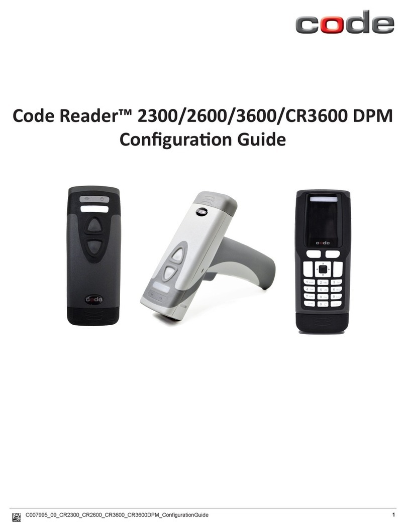
Code
Code Reader 2300 User manual
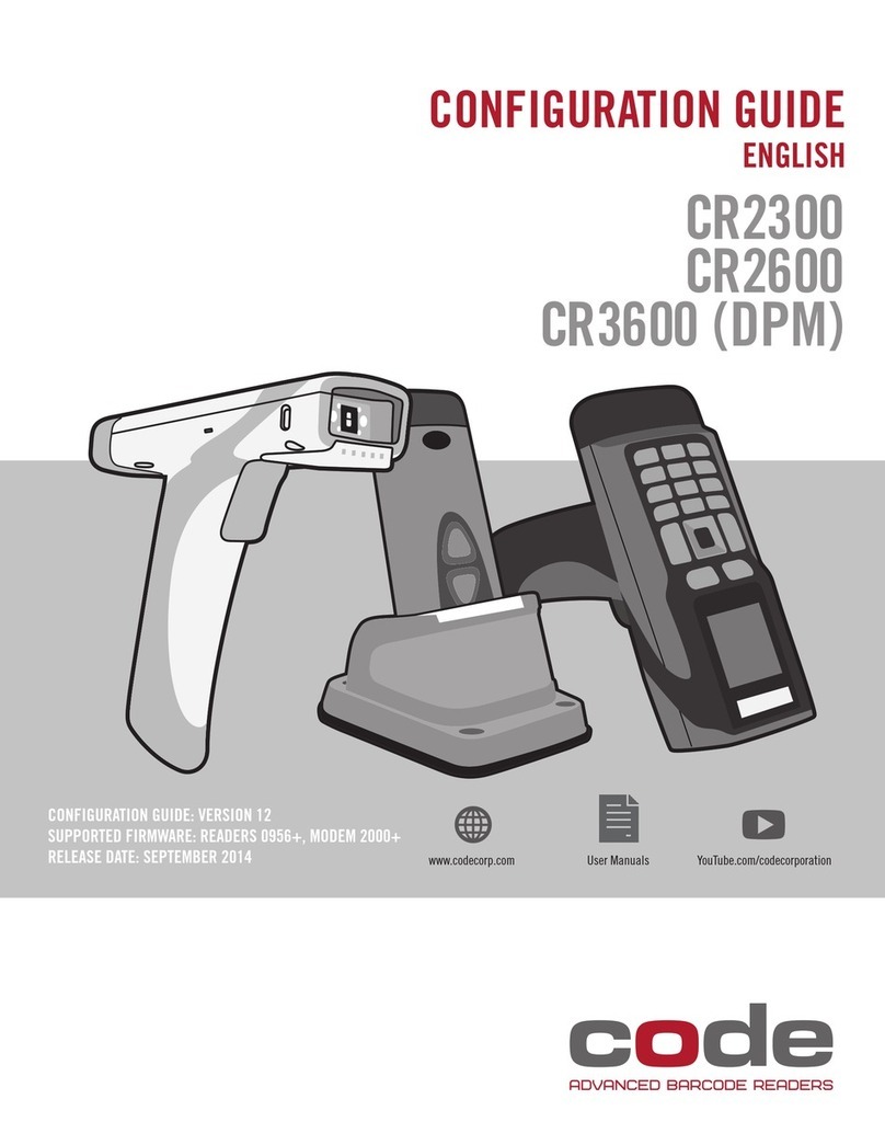
Code
Code CORTEXJPOS CR2300 User manual
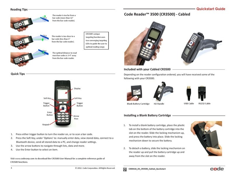
Code
Code Code Reader CR3500 User manual

Code
Code CR5200 User manual
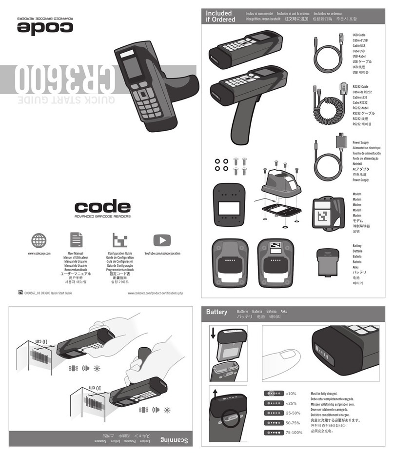
Code
Code CR3600 User manual
Code
Code CR1000 User manual
Code
Code Reader 1200 User manual
Code
Code Reader 2300 User manual
Code
Code CR3600 User manual
Code
Code CR1400 User manual
Code
Code CR900FD User manual
Code
Code CR1500 User manual
Code
Code CORTEXJPOS CR5000 User manual
Code
Code Code Reader 1400 User manual
Code
Code CORTEXJPOS CR2300 User manual
Code
Code CR4405 User manual
Code
Code Code Reader 1000 User manual

Code
Code CR821 Series Quick setup guide
Code
Code CR1000 User manual
Code
Code 2600 User manual