Cobra 29 LTD Classic User manual

Table of Contents
Contents
The CB Story.........................................................................................A1
FCC Regulations
FCC Warnings
Included Accessories
Controls & Indicators........................................................................ A2
Our Thanks to You.............................................................................A3
Customer Support
Installation
Location................................................................................................ 2
Mounting and Connection............................................................ 2
Antennas
CB Antenna .........................................................................................6
Marine Installation............................................................................ 6
Ignition Noise Interference .............................................................7
Operating Your 29 LTD Classic
Turning On Your CB......................................................................... 8
Setting Channel Selector ............................................................... 9
Calibrate For SWR (Standing Wave Ratio) ............................ 10
To Receive ........................................................................................ 13
Selecting a Channel ...................................................................... 14
S-Meter .............................................................................................. 14
NB-ANL/ANL/Off (Noise Blanker/Automatic
Noise Limiter Switch) ............................................................... 15
Bright/Dim Switch ......................................................................... 16
RF Gain Control............................................................................... 17
Setting Delta-Tune ........................................................................ 18
Setting Squelch .............................................................................. 18
To Transmit ...................................................................................... 20
Setting Dynamike®........................................................................ 20
Transmit ............................................................................................ 21
RF Meter ............................................................................................ 22
External Speaker ............................................................................ 23
PA (Public Address)....................................................................... 24
Home And Office Set-Up ........................................................... 26
Temporary Mobile Set-Up.......................................................... 27
How Your CB Can Serve You......................................................... 28
A Few Rules You Should Know................................................. 28
Channel 9 Emergency Messages ............................................. 28
CB 10 Codes..................................................................................... 30
Frequency Ranges .............................................................................32
29 LTD Classic Specifications........................................................ 33
FCC Statement ..............................................................................34-35
Warranty Information......................................................................36
Product Service................................................................................... 37
Order Info.............................................................................................. 38
Features of This Product
• 40 CB Radio Channels
• Heavy-Duty Dynamic
Microphone
• Full 4 Watts AM RF Power Output
• SWR Calibration
• Instant Channel 9/19
• 4-Pin Front Mount Microphone
Connector
• Delta -Tune
• Switchable Automatic Noise
Limiter & Noise Blanker
• Adjustable Dynamike® Boost
• 9 Ft. Mic Cord
• RF Gain
1

Installation
Installation
Location
32
Mounting and
Connection
Mounting and Connection
Hold the radio with the mounting bracket
in the exact desired location. If there is no
interference, remove the bracket and use it
as a template to mark the location for the
mounting screws.
Location
Plan location of transceiver and microphone
bracket before starting the installation.
Select a location that is convenient for operation,
yet does not interfere with the driver or passenger.
The transceiver is usually mounted to the
underside of the dash with the microphone
bracket beside it.
Note
The transceiver is held in
the universal mounting bracket
by two thumbscrews which
allow for adjustment at a
convenient angle.
The bracket includes two
self-tapping screws and star
washers. The mounting must
be mechanically strong,
conveniently located.
continued
Drill the holes and secure the bracket.
2
1
Connect the antenna cable plug to the
receptacle marked “ANT” on the back of
the unit.
3

Installation
Installation
54
Note
For best performance, we
recommend the radio be
connected directly to the
battery.
Note
Before installing the CB
radio, visually check the
vehicle’s battery connection
to determine which terminal is
positive or negative.
A negatively grounded vehicle
has its negative lead grounded
to the chassis.
Note
Connecting to an accessory
fuse prevents the unit from
being left on accidentally, and
also permits operating the unit
without running the engine.
Connect the red lead of the DC power cord to
the positive post of the battery or to an
accessory 12 volt fuse.
Connect the black lead to the of the DC power
cord to the negative post of the battery or to
the vehicle chassis.
4
5
Plug the power cord into the jack marked
“Power” on the back of the unit. Be sure to
observe polarity markings.
Mount the microphone
bracket on either side of
the radio (driver’s left)
using the two supplied
screws. Bracket should be
placed under the dash
so the microphone is
readily accessible.
6
7
Attach the 4-pin microphone cable to the
connector on the front of the radio and install
the microphone on bracket securely.
8
CH19
NOR
Note
If the microphone is not
connected, audio will not be
heard at the speaker.

Ignition Noise Interference
Antennas
Use of a mobile receiver at low signal levels is
normally limited by the presence of electrical
noise. The primary source of noise in automobiles
is from the alternator and ignition system.
Typically, when signal level is adequate, the
background noise does not present a serious
problem. Also, when extremely low level signals
are being received, the transceiver may be
operated with the vehicle’s engine turned off.
The unit requires very little current and therefore
will not significantly discharge the vehicle’s
battery.
Even though the Cobra 29 LTD Classic has an
automatic noise limiter, in some installations
ignition interference may be high enough to
make good communications impossible. Many
possibilities exist and variations between vehicles
require different solutions. Consult your COBRA
dealer or a 2-way radio technician for help in
locating the source of a severe noise.
CB Antenna
Since the maximum allowable power output of
the transmitter is limited by the FCC, the antenna
is critical in affecting transmission distance. Only
a properly matched antenna system will allow
maximum power output. Cobra loaded type
antenna models are highly recommended for
most installations. Consult your Cobra dealer
for further details, or visit our website:
www.cobra.com
Marine Installation
The transceiver will not operate at maximum
efficiency in a boat without a ground plate,
(unless it has a steel hull). Before attempting
installation , consult your dealer for information
regarding an adequate grounding system and
prevention of electrolysis between fittings in the
hull and water.
CB Antenna
7
Note
For optimum performance
in passenger cars the ideal
antenna location is on the
center of the roof. Second
choice is on the
center of the trunk.
Note
Because many newer trucks
feature fiberglass door skins,
the outside mirror must be
grounded to the chassis via a
ground strap when antenna is
mounted on the mirror bracket.
Note
3-way Combination
Antennas are also available
which allow operation of
all three bands (AM-FM &
CB), using a single antenna.
However, this type of antenna
usually results in less than
normal transmit and receive
range when compared to a
standard-type “Single Band”
CB antenna.
6
1
A standard antenna connector is provided
on the transceiver for easy connection.

The CB/PA button should be in the
CB position.
Operation
9
Operation
Turning On Setting Channel
Selector
8
Turning On
Make sure the power cord, antenna and
microphone are connected to their proper
connectors before starting.
Setting Channel Selector
2
1
Rotate the On/Off Volume knob clockwise to
a normal listening level.
Set the CH9/CH19/NOR switch to NOR.
1
CH19
NOR
CH19
NOR
Select one of forty channels and adjust the
volume. The selected channel is indicated by
the LED readout directly above the channel
selector knob.
2

CH19
NOR
Operation
Operation
Calibrate For
SWR (Standing
Wave Ratio)
1110
Note
Antenna Indicator LED
will illuminate RED when
transmitting if the
SWR is high.
Note
Calibration must be made in an
open area (never in a garage).
Vehicle doors must be closed.
No one should be standing near
the antenna. (See your antenna
directions for more complete
information).
continued
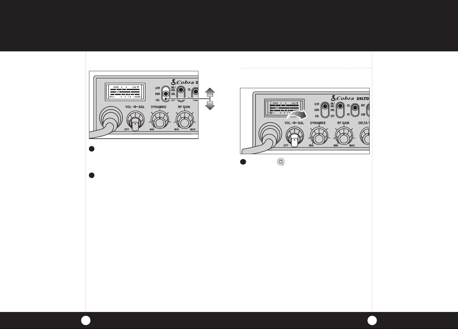
Switch to the CAL position.
2
1
Calibrate for SWR (Standing Wave Ratio)
SWR meter calibration is required to accurately
measure the SWR of the connected antenna
system. Careful adjustment is critical to obtain
best accuracy.
Select channel 20.
Push and hold the mic button.
3
While holding the mic
button adjust the
SWR CAL knob so the
meter needle swings
to the CAL mark on
the right side of the meter.
4
CH19
NOR

Operation
13
Operation
12
Note
The reading will be slightly
higher on Channels 1 and 40
compared to Channel 20.
Note
When switched to SWR position
the meter needle should
ideally be as far to the left as
possible. Anything over 3 is
not acceptable. The antenna
indicator will light. A slight
antenna height adjustment
(higher or lower) may be
required. Repeat recalibration
steps.
Repeat the same steps two through five
on Channel 1 and 40. This will check SWR for
all channels.
6
While still holding down the mic button, set
the S/RF SWR CAL switch to the SWR position,
to read the SWR reading.
5
Rotate the On/Off Volume knob clockwise.
The green RX/TX LED will be illuminated.
To Receive
1
CH19
NOR
To Receive

The S/RF-SWR-CAL switch must be in the
S/RF position to read the meter.
Operation
15
Operation
14
1
S-Meter
S-Meter
Swings proportionately to the strength of an
incoming signal when receiving.
Switch to
NORMAL to select a desired channel.
1
Selecting A
Channel
Selecting A Channel
CH19
NOR
CH19
NOR
NB-ANL/ANL/OFF
(Noise Blanker/
Automatic Noise
Limiter) Switch
Note
The RF noise blanker is very
effective in reducing repetitive
noises such as ignition
interference.
When switched to ANL the Automatic Noise
Limiter is activated. This helps reduce noise
created by the vehicle’s electronics.
When switched to NB/ANL position the RF
Noise Blanker is also activated, providing
increased noise filtration.
When switched to OFF position all noise
filtration will be turned off.
NB-ANL/ANL/OFF (Noise Blanker/Automatic
Noise Limiter) Switch
1
Select one of forty channels.
2

Operation
Operation
1716
RF Gain Control
Bright/Dim
Switch
RF Gain Control
The RF Gain is used to optimize the reception in
strong or weak signal areas.
Bright/Dim Switch
Switch to BRT or DIM to control the
brightness of the channel indicator and
multi-function meter for day or nighttime
driving.
CH19
NOR
Rotate the RF Gain knob counterclockwise
to reduce gain in strong signal areas. In weak
signal areas turn clockwise to increase the gain.
CH19
NOR
1
1

Full clockwise rotation closes the gate
allowing only very strong signals to enter.
Full counterclockwise rotation opens the
“gate” allowing all signals in.
To achieve the Desired Squelch Setting (DSS),
turn the Squelch control counterclockwise
until you hear noise. Now turn the control
clockwise just until the noise stops. This is the
DSS setting.
Setting Delta-Tune
Delta-Tune functions as a “fine tune” control
enabling you to capture a more readable signal,
as well as eliminate adjacent channel interference.
Setting Squelch
Squelch is the “control gate” for incoming signals.
19
Setting
Delta-Tune
18
Operation Operation
1
2
1
3
Rotate Delta-Tune knob to the center
position for optimum tuning.
CH19
NOR
Gate open
Gate set to Desired
Squelch Setting (DSS)
Gate closed
CH19
NOR
CH19
NOR
Setting Squelch
CH19
NOR
Other manuals for 29 LTD Classic
3
Table of contents
Other Cobra Radio manuals

Cobra
Cobra UK 29 LTD ST User manual

Cobra
Cobra 38 WX ST User manual

Cobra
Cobra 29 LX OEM B User manual

Cobra
Cobra 75WXST User manual

Cobra
Cobra MR F57W User manual

Cobra
Cobra 29 LTD Series User manual
Cobra
Cobra SoundTracker INTL75 User manual

Cobra
Cobra 29 LX LE User manual

Cobra
Cobra microTALK FRS 307-2 VP User manual

Cobra
Cobra HH 50 WX ST User manual

Cobra
Cobra 200GTL DX User manual

Cobra
Cobra 29 LTD BT User manual

Cobra
Cobra CIR2000A User manual

Cobra
Cobra 25 LTD ST User manual

Cobra
Cobra 29 LX EU User manual

Cobra
Cobra Cobra 25 NW ST User manual

Cobra
Cobra GR 29 LTD ST User manual

Cobra
Cobra 29 LTD NW User manual

Cobra
Cobra 19 DX IV User manual

Cobra
Cobra 148GTL-DX User manual