Clear-Com PL-PRO EF-1M User manual

INSTRUCTION MANUAL
EF-1M
INTERFACE

2002 Clear-Com Intercom Systems
All Rights Reserved
Part Number 810282 Rev. A
Clear-Com Intercom Systems
4065 Hollis Street
Emeryville, CA 94608-3505
U.S.A
Clear-Com is a registered trademark of Clear-Com Intercom Systems.
The Clear-Com Logo is a registered trademark of Clear-Com Intercom Systems.
Matrix Plus is a registered trademark of Clear-Com Intercom Systems.
RTS is a registered trademark of Telex Communications, Inc.
Fiber Options is a registered trademark of Fiber Options, Inc.

EF-1M INTERFACE i
CONTENTS
QUICK START 1-1
OPERATION 2-1
Description 2-1
Connecting a Party-Line Channel to a Matrix Frame Port 2-1
Converting a Party-Line Channel to 4-Wire Audio 2-3
Front Panel Controls 2-7
Rear Panel Settings and Connectors 2-9
INSTALLATION 3-1
Connecting the EF-1M Interface 3-1
Connecting the EF-1M to a Matrix Port 3-1
Connecting the EF-1M to a Modem 3-2
Connecting the EF-1M to RTS-TW Equipment 3-5
Other Connections 3-5
Levels 3-6

ii EF-1M INTERFACE
Nulling 3-7
Adjusting the Null 3-8
Troubleshooting Tips for Nulling 3-9
Internal Adjustments 3-10
TRANSMISSION METHODS 4-1
Direct Connection 4-1
Fiber-Optic 4-2
Other Methods 4-4
MAINTENANCE 5-1
Troubleshooting Tips 5-1
Block Diagram 5-6
Component Layout 5-7
Bill of Materials 5-8
GLOSSARY 6-1
SPECIFICATIONS 7-1

EF-1M INTERFACE iii
CLEAR-COM LIMITED WARRANTY 8-1
Factory Service 8-2
Warranty Repair 8-3
Non-Warranty Repair 8-3

iv EF-1M INTERFACE

EF-1M INTERFACE 1-1
QUICK START
1. Unpack the unit(s) and inspect for any damage that may have occurred during
shipping.
2. Attach the connection diagram label to a convenient surface, such as the bottom of the
EF-1M unit.
3. To connect the EF-1M directly to a Clear-Com Matrix (MX+3, MX+2) frame port,
connect an RJ-45 cable from the RJ-45 connector on the EF-1M rear panel to the
Matrix port.
For all other connections, wire the DB-15 connector on the EF-1M’s rear panel to the
other interfaces being used (fiber-optic, direct connection to another EF-1M, etc.).
Take care to wire to the correct pin assignments, including selection of Clear-Com or
RTS-type operation. Follow the manufacturer’s recommendations for cable type.
4. Set the rear-panel mode switches according to Table 1 in Chapter 2.
5. Repeat for each location.
6. Connect the respective party-line systems at each location to the 3-pin XLR on each
EF-1M’s back panel.
7. If there is a proper RS-422 data connection, or if the Matrix Direct mode switch is on,
the amber LED on the EF-1M unit’s front panel will illuminate steadily.
Follow these instructions
to quickly get the
system up and running.
1

EF-1M INTERFACE 1-2
8. Plug in the test earpiece and set the null for each location using the procedure
described in “Adjusing the Null” in Chapter 3. Adjust the null on other stations and
beltpacks if required.
9. Adjust send and receive levels at each location as described in “Levels” in Chapter 3.

EF-1M INTERFACE 2-1
OPERATION
Thank you for choosing this Clear-Com Intercom Systems product.
The EF-1M 4-Wire and Matrix Direct Interface is a flexible and powerful tool for
connecting 2-wire intercom systems or stations together over various 4-wire transmission
media. The EF-1M Interface can also connect a 2-wire intercom system directly to a
Clear-Com Matrix (MX+3, MX+2) frame port.
Please read this manual completely to better understand the EF-1M Interface. For
questions not addressed in this manual, contact your dealer, distributor, or Clear-Com
directly. Our applications support and service people are ready to help.
DESCRIPTION
CONNECTING A PARTY-LINE CHANNEL TO A MATRIX FRAME PORT
An EF-1M Interface can connect a channel of standard or TW party line directly to a
Clear-Com Matrix (MX+3, MX+2) frame port, allowing the party-line intercom to be
EF-1M units connect
2-wire intercom stations
or systems together
over various
transmission media.
2
2-2 EF-1M INTERFACE
located at quite a long distance from the Matrix frame. At the same time, the EF-1M
interfaces a DC-voltage call signal or 20-kHz call signal to the Matrix.
The EF-1M is recognized by the Matrix as a Clear-Com CCI-22 Interface. It provides the
same function as the CCI-22 Interface with the following exceptions:
• the EF-1M supports only one channel.
• the EF-1M also supports the 20-kHz call signal protocol.
• the EF-1M is a stand-alone unit and does not require an interface frame.
NOTE: The EF-1M must be powered from the party-line connection.
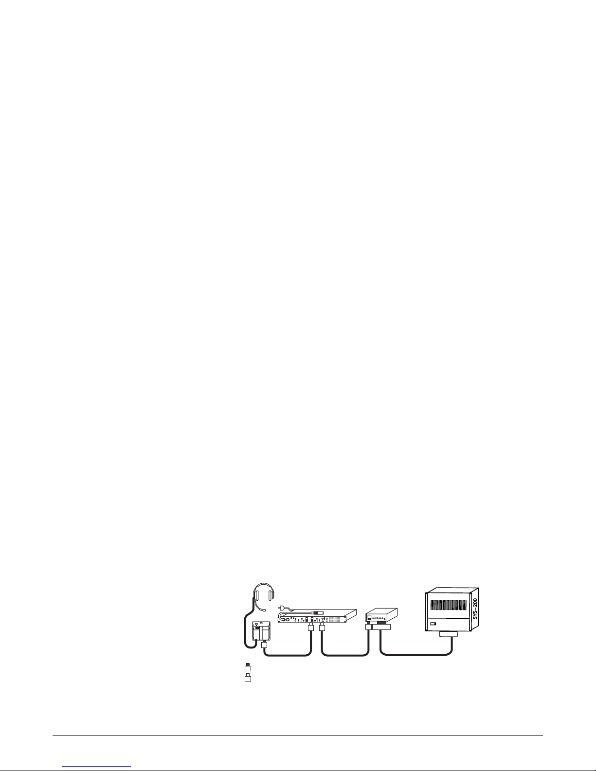
Figure 1: Connecting a party-line channel to a Matrix intercom
3
3
= Male 3-Pin XLR
= Female 3-Pin XLR
Party-Line Intercom EF-1M
33
3
3RJ-45
RJ-45
Matrix
Table of contents
Other Clear-Com Recording Equipment manuals

Clear-Com
Clear-Com CCI-22 User manual

Clear-Com
Clear-Com Eclipse IFB-104 User manual

Clear-Com
Clear-Com ECLIPSE MATRIX User manual

Clear-Com
Clear-Com Eclipse 13.1 HX User manual

Clear-Com
Clear-Com FOR-22 User manual

Clear-Com
Clear-Com LQ series User manual

Clear-Com
Clear-Com FIM-108 User manual

Clear-Com
Clear-Com LQ series User manual

Clear-Com
Clear-Com ECLIPSE AES-6 User manual

Clear-Com
Clear-Com RS-100A Troubleshooting guide


