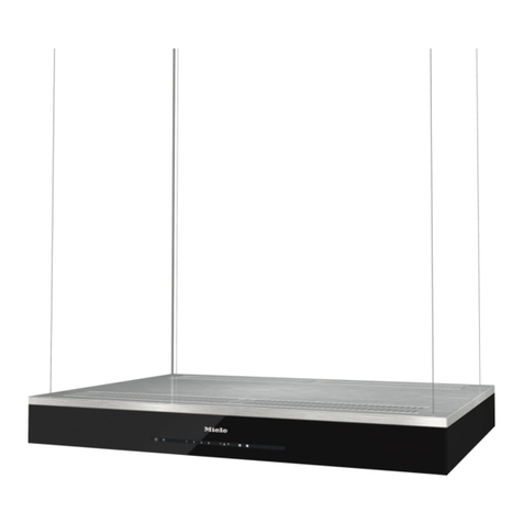
Chambers MVW206SS User manual

INSTALLATION AND USER MANUAL
Model: MVW206SS
* Important: Read the complete manual carefully
before installation*
For accuracy, measurements and rough openings should be
done based on the actual hood.

2
CONTENTS
INTRODUCTION.......................................................................3
SAFETY INFORMATION............................................................3
TOOLS & PARTS.......................................................................5
INSTALLATION.........................................................................6
OPERATION.............................................................................12
MAINTENANCE........................................................................13
TROUBLESHOOTING................................................................14
ENVIRONMENTAL PROTECTION..............................................15
WARRANTY..............................................................................16
CONTACT INFO.........................................................................17

3
INTRODUCTION
Thank you for choosing this cooker hood.
This instruction manual is designed to provide you with all required
instructions related to the installation, use, maintenance, and warranty of the
appliance. Please read this instruction manual carefully before installation and
operating your range hood. This range hood is made from high quality
materials and has a streamlined design. Equipped with a powerful electric
motor and centrifugal fan, your range hood will provide excellent ventilation
and low noise operation.
1. IMPORTANT SAFETY INFORMATION
Intended for Domestic Kitchen Use Only
Warning:
TO REDUCE THE RISK OF FIRE, ELECTRICAL SHOCK OR PERSONAL INJURY,
PLEASE OBSERVE THE FOLLOWING:
1. Installation and electrical work must be done by a qualified TECHNICIAN in
accordance with all applicable codes and standards.
2. If the supply cord is damaged, it must be replaced by the manufacturer, its service
agent or a similarly qualified person to avoid a hazard. Any modifications that may be
required to the home’s electrical system for the installation of the range hood must
only be made by qualified electricians.
3. Before servicing or cleaning unit, switch power off at the service panel.
Lock panel to prevent power from being switched on accidentally.
4. Use this unit only in the manner intended by the manufacturer.
5. Sufficient air is needed for combustion and exhausting of gases through the
chimney of fuel burning equipment to prevent back drafting. Follow the heating
equipment manufacturer’s guidelines and safety standards such as those published
by the National Fire Protection Association (NFPA), and the
American Society for Heating, Refrigeration and Air Conditioning Engineers
(ASHRAE), and the local code authorities.
6. When cutting or drilling into wall or ceiling, be careful NOT to Damage existing
electrical wiring and other hidden utilities.

4
7. Ducted fans must always be vented to the outdoors.
8. To reduce the risk of fire, use only metal ductwork.
9. This unit must be grounded.
TO REDUCE THE RISK OF A RANGE TOP GREASE FIRE:
1. Never leave surface units unattended at high settings. Boil overs cause smoking
and greasy spillovers that may ignite. Heat oils slowly on low or medium settings.
2. Always turn hood ON when cooking at high heat or when flambéing food (i.e.
Crepes Suzette, Cherries Jubilee, Peppercorn Beef Flambé’).
3. Clean ventilating fans frequently. Grease should not be allowed to accumulate on
fan or filter.
4. Use proper pan size. Always use cookware appropriate for the size of the surface
element.
TO REDUCE THE RISK OF INJURY TO PERSONS IN THE EVENT OF A RANGE
TOP GREASE FIRE, OBSERVE THE FOLLOWING:
1. SMOTHER FLAMES with a close-fitting lid, cookie sheet or metal tray, and then turn
off the burner. If the flames do not go out immediately, evacuate and call the fire
department.
2. NEVER PICK UP A FLAMING PAN. –You may be burned.
3. DO NOT USE WATER, including wet dishcloths or towels –a violent steam explosion
may result.
4. ONLY USE AN EXTINGUISHER IF:
• You know you have a Class ABC extinguisher and you already know how to
operate it.
• The fire is small and contained in the area where it started.
• The fire department is being called.
• You can fight the fire with your back to an exit.

5
2. TOOLS AND PARTS REQUIREMENTS
Electrical drill or ratchet driver
1/2” drill bit for drilling pilot holes
1 ¼” drill bit for drilling electrical wiring
access hole.
Screwdrivers: Philips & Straight blade
Pliers
Tape measure or ruler and pencil
Electrical supplies for wiring
Aluminum foils tape and/or duct tape
Hammer
Jigsaw or saber saw
Stud finder
Installation parts
Part
QTY
Photo
Bracket for
body
1pcs
Bracket for
upper chimney
1pcs
Bracket for
lower chimney
1pcs
Screw: ST4*8
4pcs
Screw:
ST4.0*30
9pcs
Wall anchor:
9pcs
Parts Supplied
Body 1 pcs
Body bracket 1 pcs
Chimney 2 pcs
Chimney mounting bracket 2 pcs
Installation manual 1 Set
Air outlet
(In bag or on body) 1 Set
Exhaust pipe 1 Pcs
Installation manual 1 Pcs
Screw bag 1 bag
Disclaimer: Screws many vary from
model to model.
LOCATION REQUIREMENTS
IMPORTANT: Observe all governing codes and
ordinances. Have a qualified technician install the
range hood. It is the installer’s responsibility to comply
with installation clearances specified on the
model/serial rating plate.
Canopy hood's location should be away from strong
draft areas, such as windows, doors, and strong
heating vents.
Cabinet opening dimensions that are shown must be
used. Given dimensions provide minimum clearance.

6
3. INSTALLATION (Before You Start...)
1. Read this manual carefully and completely.
2. Chambers® range hoods conform to ETL/CSA standards. Check your local
building codes for any additional requirements.
3. The appliance has been manufactured as Class I, therefore a ground
connection is necessary. A 110/120V power cord with plug is provided. The
range hood must be installed so that the plug is easily accessible.
4. This appliance has been designed for use in both ducted and recirculating
modes, follow the appropriate installation method. (For recirculation mode
a kit is required –not included. Contact Chambers® to determine if a kit is
available for your hood.)
5. Your cooker hood can be connected as below by means of an extraction
duct (enamel, aluminum, flexible pipe or inflammable material with an
interior diameter of 6”.)
6. Before installation, turn the unit off and unplug it from the outlet.

7
7. The cooker hood should be placed at a distance of 2-3ft (Fig C.) above the
cooking surface for best effect. Check your building code for min and max
installation heights.
4. INSTALLATION (EXTERIOR VENTILATION):
When the range hood is in operation, the negative pressure in the room must not
exceed 4 Pa (4×10⁻⁵ Bar)
1. Drill 3 x 8mm holes to accommodate the bracket. Screw and tighten the
bracket onto the wall with the screws and screw plugs provided. Ensure
that you affix the bracket to a wall stud or mounting plate.

8
Holes on wall
Screw
(4mm x 30mm)
Screw plug
Wall bracket
2. Lift the cooker hood and hang it onto the wall bracket hooks.
Cooker hood
Wall bracket
3. After hanging the hood on the bracket, remove the filters, mark 2 holes
inside the hood for safety screws. After marking, remove the hood and drill
two holes. Insert 2 pcs of Wall Plugs and finally fix the safety screws with 2
screws ST4x30mm

9
4. Fix the one-way-valve to the air outlet of the cooker hood. Then, attach the
exhaust pipe to the one-way-valve as shown below.
Exhaust pipe
Cooker hood
5. CHIMNEY INSTALLATION
1. Place the upper chimney into the lower chimney.
2. Use 2 pcs ST4x8mm screws to attach lower and upper chimney together. Before
attaching the bracket to the chimney, decide the location of lower chimney
bracket fixing holes for fixing the lower chimney bracket in the later steps.
3. Do not over tighten the screws
4. Make sure the upper chimney can be telescopically adjusted after assembly.

10
5. Drill 2 holes to accommodate plate II. Screw and tighten plate II onto the wall
with two screws and wall plugs provided. Slide the upper chimney up to the
correct height and affix the upper chimney with plate II via 2 x ST4x8mm screws.
6. Fix the lower chimney with the hood with 2 screws ST4x8mm
Table of contents
Other Chambers Ventilation Hood manuals