Casio Cassiopeia IT-2000 User manual

Data Collector
Colector de Datos
Datenerfassungsgerät
Collecteur de Données
User’s Guide
Guía del usuario
Bedienungsanleitung
Mode d’emploi
• Congratulations upon your selection of
the CASIO IT-2000 Data Collector.
• Be sure to familiarize yourself with the
basic operations described in this
manual before actually trying to
operate the Data Collector.
• Enhorabuena por la selección del
colector de datos IT-2000 CASIO.
• Antes de intentar utilizar este colector
de datos, familiarícese con las
operaciones básicas descritas en este
manual.
• Mit dem Datenerfassungsgerät CASIO
IT-2000 haben Sie eine gute Wahl
getroffen.
• Bitte machen Sie sich mit den in
diesem Handbuch beschriebenen
Grundfunktionen vertraut, bevor Sie
beginnen, mit dem
Datenerfassungsgerät zu arbeiten.
• Nous vous remercions d’avoir choisi le
Collecteur de Données Casio IT-2000.
• Veuillez vous familiariser avec les
démarches de base, décrites dans ce
manuel, avant d’essayer d’utiliser le
Collecteur de Données.
Imprimé au Japon
Printed in Japan
AB9906-0003503B
Printed on recycled paper.
Imprimé sur papier recyclé.
Gedruckt auf wiederverwertetem Papier.

E-2
• Information in this manual is subject to change without notice.
• CASIO shall have neither liability nor responsibility to any person or entity with respect to
any loss or damages arising from the information contained in this book.
• This manual does not provide information about programming and downloading. See other
manuals coming with IT-2000 for information about these subjects.
• All efforts were made to create this manual as complete and as accurate as possible but in
case our in user find unclear explanation or errors, we would appreciate remarks and
suggestions communicated by users.
CONTENTS
Introduction ............................................................E-4
Precautions ...........................................................................E-4
IT-2000 Series System Configuration...................E-6
General Guide.........................................................E-8
Installing and Removing Batteries .....................E-10
Main power supply ..............................................................E-10
Backup batteries..................................................................E-12
Position of the Keys.............................................E-14
Position of stroke keys ........................................................E-14
Touch key panel ..................................................................E-15
System Initialization Routine ..............................E-18
Charging the Battery Pack ..................................E-19
To charge the battery pack ..................................................E-19
To charge battery packs using the Charger.........................E-20
Attaching the Neck Strap ....................................E-21
Data Communication ...........................................E-22
Exchanging Data Between Two Data Collectors.................E-22
Exchanging Data with a Personal Computer.......................E-22
IT-2000’s Specifications.......................................E-23
Charger Specifications ........................................................E-23

E-3
IT-2060IOE Optional Optical
Communication Unit .......................................E-24
General Guide .....................................................................E-24
Connecting the Optical Communication Unit
to a Power Source .........................................................E-26
Daisy Chaining Optical Communication Units .....................E-28
DIP Switch Settings .............................................................E-29
IT-2060IOE Optical Communication Unit Specifications .....E-30
Handling Bar-Code Reader .................................E-31
Connecting the bar-code reader..........................................E-31
Detaching bar-code reader..................................................E-31
Using a bar-code reader......................................................E-31
Bar-Code Reader Specifications .........................................E-35
Using PC Cards ....................................................E-36
To load a memory card into the Data Collector ...................E-36
To remove a card from the Data Collector...........................E-37
Operating Precautions.........................................E-38
Notice ....................................................................E-39
CASIO ELECTRONICS CO., LTD.
Unit 6, 1000 North Circular Road
London NW2 7JD, U.K.
E-4
Introduction
In order to maintain and use the Data Collector, keep in mind these precautions.
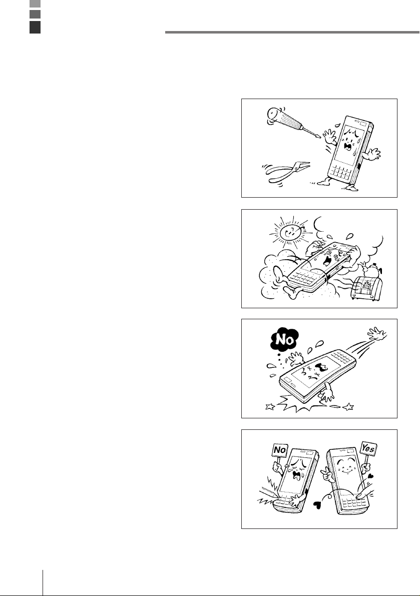
Precautions
•This product is made of precision parts so do
not try to disassemble by yourself.
•Do not expose the Data Collector to excessive
heat or cold. Do not place it direct sunlight,
dusty or extremely humid areas. The utilization
of the power supply in moisture places is
forbidden. Do not leave the Data Collector on
hot places, such as car trunk or seats.
•Do not expose it to mechanical shocks,
especially during running programs, recording
or booting up because it can cause permanent
loss of data and damage to the LCD.
•Stroke keys must be pressed with care.
Use only the special touch panel pen for
working with the touch panel.
Do not apply excessive force or use sharp
objects for this purpose because in that way
you can damage the touch panel or internal
circuitry.
E-5
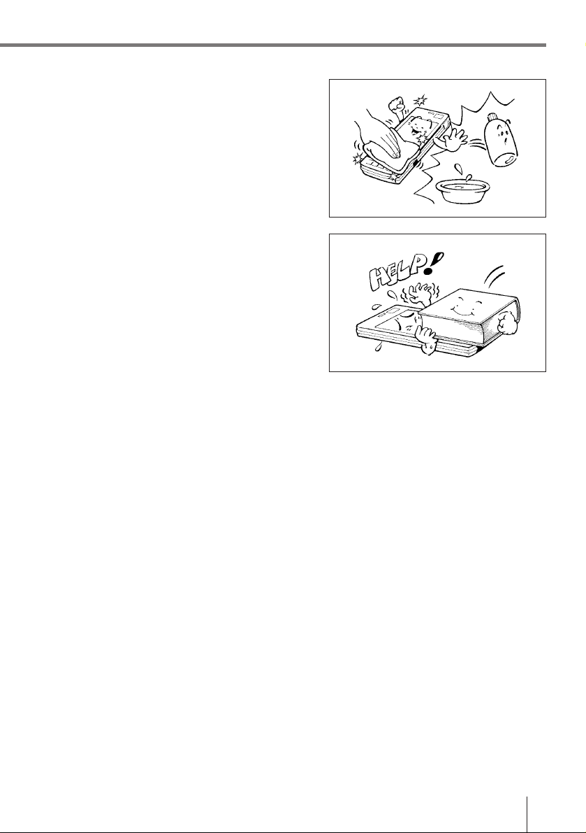
•Blow off dust with a blower brush or a soft
cloth.
No utilization of liquid- or spray-cleansing
agents is allowed. It may deform the keys or
the body of the Data Collector. The Data
Collector must not come in contact with
chemicals and gasoline.
•Do not place heavy objects on the Data
Collector.
Important! CASIO does not accept any responsibility for possible data loss caused
during, or connected with, usage of the Data Collector.
E-6
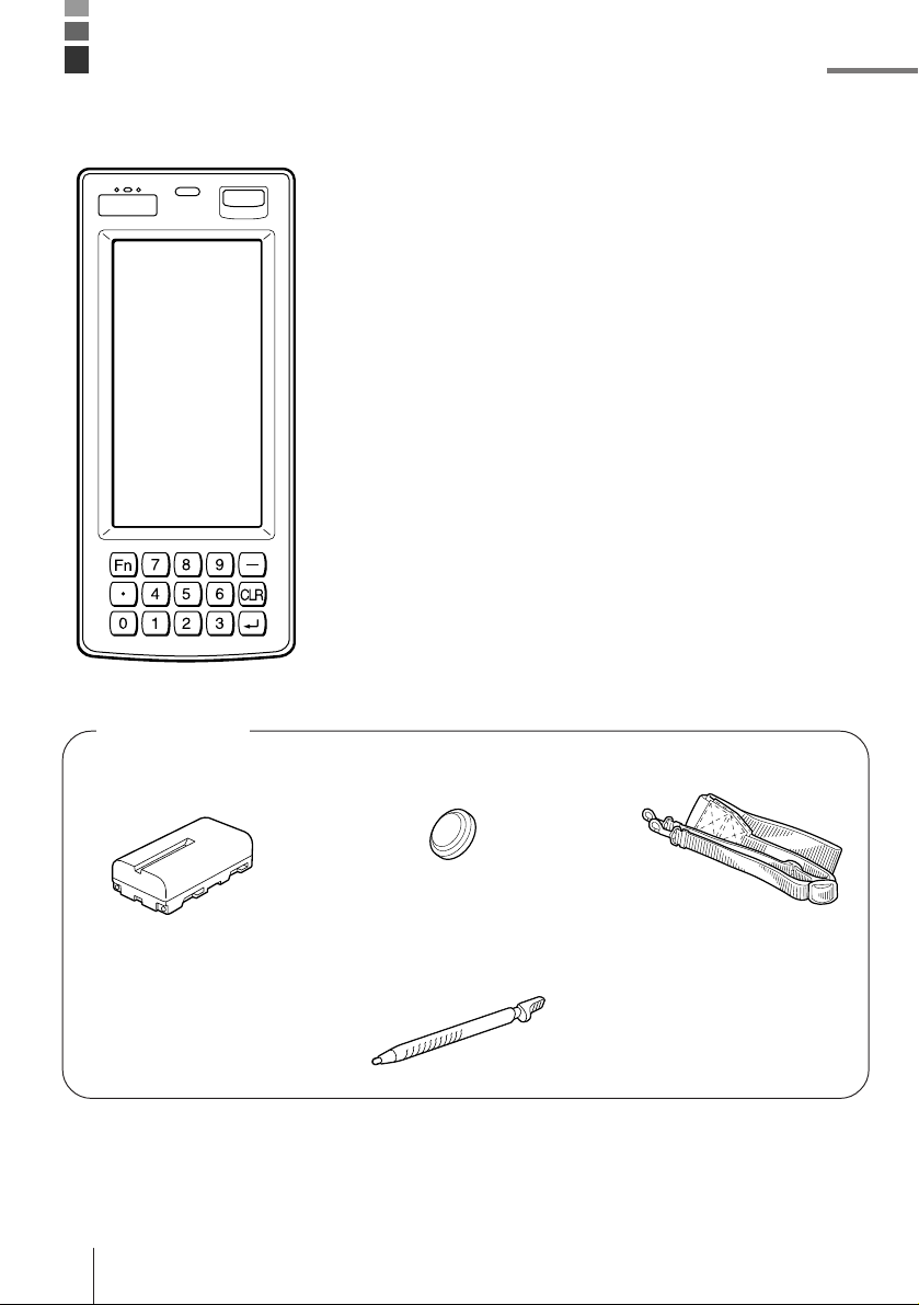
IT-2000 Series System Configuration
• Backup Lithium Battery
• Stylus
Placed to the right side of
the Data Collector
Accessories
• Lithium ion Battery
Pack • Neck Strap
• Manual
E-7
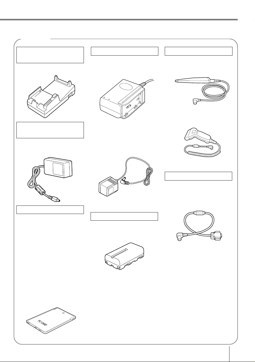
Bar-code reader
DT-9650BCR
DT-9656BCR
Cable
DT-9689AX
(between Data Collector
and personal computer)
DT-881RSC
(modem-used)
DT-882RSC
(cross connection, male)
DT-883RSC
(cross connection, female)
DT-887AX
(AX-used, cross connection)
DT-888RSC
(Optical Communication
Unit-used)
Charger
DT-9021CHGE
DT-9020ADP-G
DT-9020ADP-U
Lithium ion Battery Pack
DT-9023LI
Options
Optical
Communication Unit
IT-2060IOE
AC adaptor for
Optical
Communication Unit
DT-825ADP-G
DT-825ADP-U
PC Cards
DT-635MC (SRAM 256KB)
DT-636MC (SRAM 512KB)
DT-637MC (SRAM 1MB)
DT-638MC (SRAM 2MB)
DT-9031BFMC
(FROM 4MB)
DT-9032BFMC
(FROM 6MB)
DT-9033BFMC
(FROM 10MB)
DT-9034BFMC
(FROM 20MB)
E-8
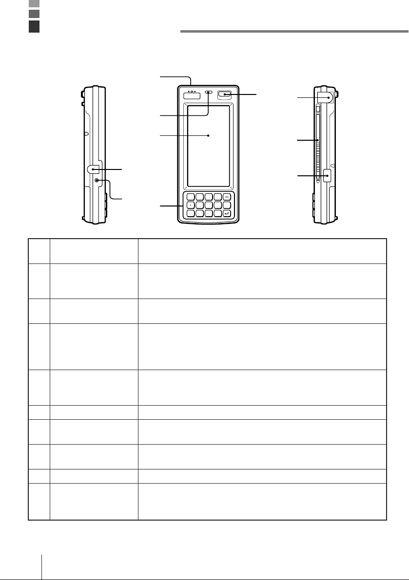
For connection of the charger to charge the lithium ion battery pack.
Protected by a cover that must be opened for connection.
Stays lit while the lithium ion battery pack is being charged, and goes
out after charging is complete. Lights momentarily when the charger
is connected even when the battery pack is charged.
Emits audible signals to confirm certain operations. Make sure that
buzzer holes are not blocked so signals can be heard.
Detects available light. This information is used to control the
backlight when the Data Collector is set up to automatically turn on
the backlight under low lighting conditions. For proper operation,
make sure this sensor is not blocked.
Display data during program execution and other operations. Also
provides touch panel keys for input by touching the screen with a
finger or the stylus that comes with the Data Collector.
10-key pad, execute key, and other keys.
Press to turn power on and off, or to restore power after operation of
auto power off.
For connection of a bar code reader or other external device.
Protected by a cover that must be opened for connection.
For touch panel operation.
Communication port for data exchange with the Optical
Communication Unit when exchanging data between two Data
Collectors.
1 Charger connector
2 Charge indicator
3 Buzzer
4 Light sensor
5 LCD/Touch panel
6 Key pad
7 Power switch
8 RS-232C Interface
Connector
9 Stylus
10 Infrared interface
General Guide
Left Front Right
0123
456
789
6
5
48
10
1
2
37
9
Fn
CLR

E-9
Top Back
Bottom
13 20
17
16
19
14
18
15
11 12
Locks optional PC card in place. Make sure this button is in the LOCK
position when using a PC card. The PC card is not detected by the
Data Collector when this button is in the LOCK release position.
Press this button (after opening the PC card slot cover and setting the
PC card lock button to lock release position) to eject a PC card
installed in the Data Collector.
Open when inserting or removing a PC card.
For connection of the neck strap.
These connectors mate with Optical Communication Unit connectors
to receive electrical power for charging of the lithium ion battery pack.
Houses the lithium battery used for memory backup.
Slide to open the battery pack cover.
Houses the lithium ion battery pack that is the Data Collector’s main
power supply.
Use a paper clip or other thin, pointed object to press this button to
launch the Data Collector’s system initialization routine.
For connection of future expansion options.
11 PC card lock button
(inside PC card slot
cover)
12 PC card eject button
(inside PC card slot
cover)
13 PC card slot cover
14 Neck strap bars
15 Charger connectors
16 Backup battery
compartment
17 Open button
18 Lithium ion battery
pack compartment
19 Initialize button
20 14-pin serial interface
connector
Note! Pressing the Initialize button clears all data and programs from memory.
Never press the Initialize switch unless absolutely necessary.
E-10
Your Data Collector is powered by a rechargeable lithium ion battery pack and a lithium
backup battery.
Main power supply
See page E-19 for details on how to recharge the battery pack.
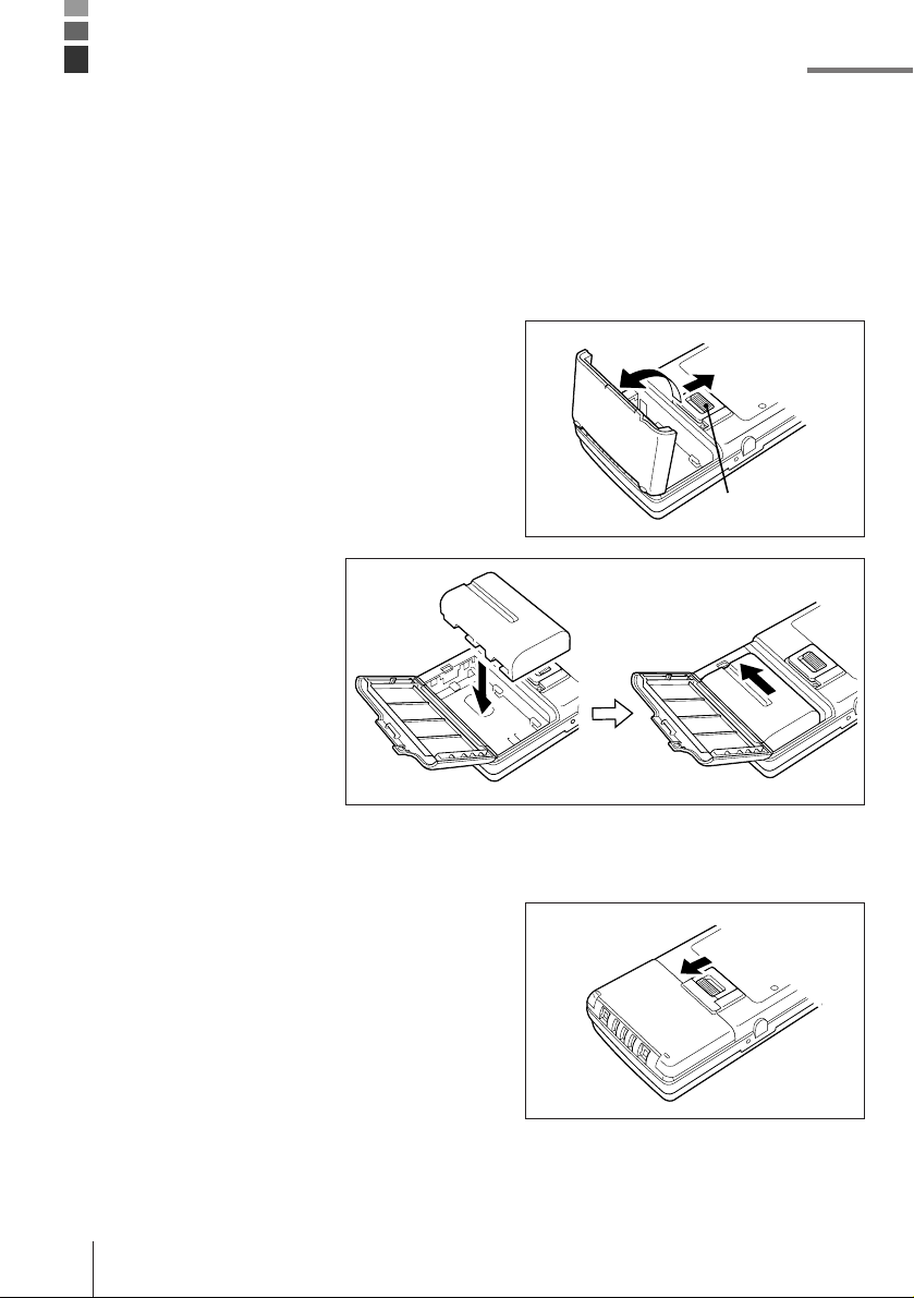
To install the battery pack
1Slide the battery pack compartment open
button in the direction indicated by the arrow
in the illustration, and open the cover.
2With the indentation of
the battery pack facing
up (so you can see it),
install the battery pack
into the compartment as
shown in the illustration.
Make sure that the
battery pack’s terminals
are facing in the correct
direction. Next, slide the
battery pack in the
direction shown in the
illustration so that it
locks into place.
3Close the battery pack compartment cover.
Close the cover and then slide the open
button in the direction indicated by the arrow
to secure the cover in place.
Note that the battery pack will not supply
power correctly unless the battery pack
compartment cover is closed securely.
Double check to make sure that the cover of
your unit is closed correctly.
Installing and Removing Batteries
Open button
Other manuals for Cassiopeia IT-2000
2
Table of contents
Other Casio PDA manuals

Casio
Casio SF-9700 User manual

Casio
Casio PV-S250 User manual

Casio
Casio PV-S250 User manual

Casio
Casio PV-250X User manual

Casio
Casio DT-X30 R-50C User manual

Casio
Casio PV-750 Plus Instruction and safety manual

Casio
Casio PV-750 Plus Instruction and safety manual

Casio
Casio DX-500TR Troubleshooting guide

Casio
Casio FA-127 User manual

Casio
Casio Cassiopeia EM-500 User manual


