careium i10 User manual

Smoke detector i10
User guide
English

2
Table of contents
1. Product overview ............................................2
2. Placement........................................................3
3. Assembly/Installation .....................................6
4. Installer settings..............................................9
5. Description of push button/LED radio.........11
6. Alarms from serial-connected device ..........12
7. Alarm test ......................................................12
8. User information...........................................13
9. Maintenance manual ....................................15
10. General information .....................................15
11. Technical data ...............................................16
12. Other..............................................................16
13. Legal information..........................................17
1. Product overview
This re alarm is approved in accordance with EN14604:2005,
the latest and most rigorous European standard for re alarms.
The unique X-Prole's optical detection chamber is particularly
sensitive to slow and smouldering res typically originating from
living rooms, bedrooms and hallways where porous materials
or textiles are present, while being highly resistant to false alarms.
The re alarm with its built-in battery has a guaranteed service
life of 10 years.

3
1.1. Product features
• Sealed built-in 10 year lithium battery.
• Approved according to EN14604: 2005 (re alarms)
• Unique X-prole detection chamber with integrated insect
screen.
• Software that maximises detection and reduces false alarms.
• Switches on automatically when clicked into place on
the radio base.
• Red LED ashes approximately every minute conrming that the
unit is powered and ready to detect a re. (Standby mode)
• If the battery is low or the re alarm has reached the end of its
service life, a beep will be emitted every minute. It is possible
to silence the alarm for ten hours by pressing the test button.
The re alarm does not need to be removed from the mounting
plate. It can be replaced at your convenience the following
day/days.
• Extra large test button for easy and complete function control.
• Reacts quickly with a strong signal (85dB at 3 metres) that
automatically resets when smoke has left the detection
chamber.
• Pause function– Silence your alarm briey, ideal for
non-emergency situations when unwanted alarms occur,
such as from steam or cigarette smoke. The red LED ashes
every 12 seconds to remind you that it has been paused and
automatically resets to active mode within 10 minutes.
2. Placement
Optical re alarms are considered to be most eective in detecting
smouldering res. Fires that can smoulder for several hours before
developing into open ame res. Examples of this type of re
could be a cigarette lying on a piece of furniture and smouldering,
or an electric cable that is overheated and eventually catches re.
Fire alarms must not be installed in kitchens or bathrooms, as
the risk of unwanted alarms increases, but preferably in a room
next to the kitchen, hall or living room.

4
Recommended placement of smoke
and heat detectors:
2.1. Where to avoid placement
1. Do not place the re alarm close to fans, as exhaust or supply
air devices can blow or suck smoke away from the alarm.
2. Do not install in or near areas with high humidity, e.g. showers,
bathrooms or kitchens where humidity exceeds 85% or where
room temperature exceeds 45° or falls below 0°, as this may
cause false alarms and/or damage the device.
3. Do not install at the top of a vaulted or sloping ceiling.
Stationary air can prevent smoke from reaching the device.
4. Do not install less than 50cm from walls and mounted light
ttings where rising heat or stationary air can prevent smoke
from reaching the alarm.
5. Do not install in areas with high insect activity.
6. Do not install in areas with high concentrations of cigarette
smoke that may cause false alarms and over time the device
may become contaminated.
SOVRUM
SOVRUMSOVRUM
VARDAGSRUM KÖK
KÄLLARE
GARAGE
MATSALKÖK
VARDAGSRUM
SOV-
RUM
FLERVÅNINGSHUS MED
FLERASOVAVDELNINGAR
SOVRUM
SOVRUM
BRANDVARNARE, MINSTA SKYDD
BRANDVARNARE, REKOMMENDERAT SKYDD
ENPLANSHUS MED
TVÅ SOVAVDELNINGAR
VI
D MONTERING I TAK,
MI
NST 50 CM FRÅN VÄGG
VID MONTERING PÅ VÄGG
(REKOMMENDERAS EJ)
15 CM FRÅN TAK
VID MONTERING I SNEDTAK
MINST 1 M HORISONTELLT
FRÅN TAKNOCK / TAKÅS
S.K. “DÖD ZON” - MED
STILLASTÅENDE LUFT
SINGLE-STOREY
HOUSE WITH
TWO BEDROOMS
BED-
ROOM
DINING
ROOM
KITCHEN BEDROOM
LIVING ROOM
BEDROOM
FIRE ALARMS, MINIMUM PROTECTION
FIRE ALARMS, RECOMMENDED
PROTECTION
MULTI-STOREY BUILDING
WITH MULTIPLE BEDROOMS
“DEAD ZONE” -
WITH STATIONARY AIR
WHEN INSTALLING ON SLOPING
CEILING AT LEAST 1 M HORIZONTAL
FROM ROOF RIDGE
WHEN INSTALLING
ON CEILING, AT LEAST
50 CM FROM WALL
WHEN INSTALLING ON
WALL
(NOT RECOMMENDED)
15 CM FROM CEILING
BEDROOM
BEDROOM BEDROOM
GARAGE
LIVING ROOM KITCHEN
BASEMENT

5
7. Do not install re alarms in kitchens, boiler rooms and garages
where smoke and dust can cause false alarms.
8. Do not install on poorly insulated walls and ceilings where
cold air boundary layers can prevent smoke from reaching
the re alarm.
9. Do not install near objects that can prevent smoke from
reaching the alarm e.g. high bookshelves.
10. Do not install closer than 150cm from uorescent tubes
that can trigger interfering false alarms when they are
switched on and o.
11. Do not cover or paint the alarm.
2.2. Additional placement information
1. At least one re alarm must be installed along escape routes
from all oors of the building.
2. The detection chamber of a smoke detector must be tted
between 2.5cm and 30cm below the ceiling.
3. Fire alarms must be installed at least 50cm from walls
or light ttings.
4. If ceiling mounting is impractical, re alarms may be installed
on walls provided that the area is no longer or wider than 10m
and the total area does not exceed 50 m2 and that:
• The smoke chamber is between 15–30cm below the ceiling.
• The bottom of the re alarm is above ventilation openings,
doors and openable windows.
• They are not mounted near or over heating systems or air
conditioning exhausts.
5. If re alarms are located in a hallway, corridor or entrance,
the devices must not be more than three metres from any
bedroom door to improve audibility through closed doors.
6. In large areas, a re alarm should be no longer than 7.5 metres
away from any point in the ceiling of any room, hall or corridor.
7. In order to provide as early a warning as possible, re
alarms should be installed in all rooms of your home and
interconnected where possible. (Except for the areas indicated
in section 2 under the heading “Where to avid placement”
as above).

6
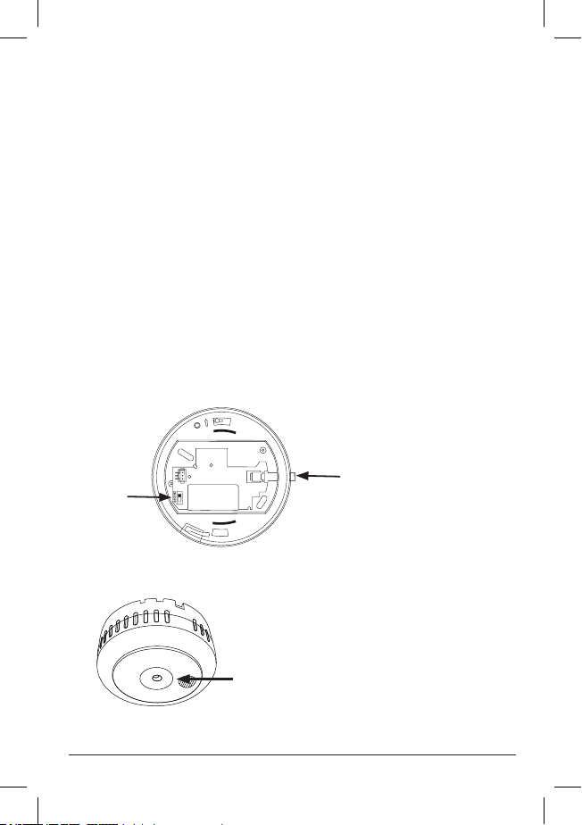
3. Assembly/Installation
Do not store devices at temperatures below 0°C and above 45°C
as this may cause unwanted alarms and disturbances after initial
installation. However, these will stop after a short time when
the device has become acclimatised to the new temperature.
Prolonged periods under these conditions will reduce the lifetime
of the device and may void the warranty.
Separate the device from the mounting plate. The re alarm
is supplied switched o with the radio base not attached.
If the device has been activated before installation, press
the small locking wedge located on the side and turn the alarm
counter-clockwise while holding the radio base. Then remove
the realarm.
Decide where to install the device. See previous section. Always
ensure that surfaces do not contain hazardous materials, e.g.
asbestos, water or electrical wires before drilling. The enclosed
screws are suitable for use in wood, and screws and plugs are
used for plasterboard and concrete. For some installations, the
installer may need to use another solution such as double-sided
tape or adhesive to avoid drilling. If mounting adhesive is used,
consider the drying time before actually tting the re alarm.
If you use double-sided tape or adhesive, make sure that the
surfaces are clean, dry, at and have good adhesion. Always take
appropriate safety precautions when attaching the mounting plate
to the ceiling. Wear protective equipment, e.g. protective goggles
and a face mask when drilling.
3.1. Installing a device
N.B. If you want to use multiple devices connected
via Wi-Fi, see section 3.2.
1. Fix the base unit to the ceiling using your preferred solution.
2. Activate the radio card in the base unit: press and hold the
push button on the radio card, see Fig. 1 A. Turn on the radio
card with the power switch, see Fig. 1 B. The push button (1A)
now ashes quickly. Release the button. Press the button again.
The button will light up for a while and then go out. Theradio
card is now activated as a single unit. Connect the cable.
7
3. Align the arrow on the back of the re alarm with the
arrow inside the mounting plate, when the re alarm is
aligned correctly on the mounting plate, turn clockwise
untilthelocking wedge clicks into place. The built-in battery
will now automatically activate and the re alarm will start
up with an internal silent test.
4. Activate the radio learning mode in the personal alarm
unit/system
5. Press the test button once to send a radio message that
can be used to pair the smoke detector with the personal
alarmphone.
6. Conrm the setting on the receiver unit.
7. Congure the desired alarm type on the receiving unit.
8. Test the entire alarm chain by pressing the test button three
times within two minutes to send an alarm and wait for
the operator to respond to the alarm. See Fig 2. Remember
to alert the alarm receiver.
Fig. 1
ON/OFF
1 A
1 B
EN: Test button, control lamp
SV: Testknapp, kontrollampa
DE: Testtaste, Kontrollleuchte
NO: Testknapp, kontrollampe
ES: Botón de prueba, luz de control
Fig. 2

8
3.2. Installation of serial-connected devices
The radio card is used to connect our various devices for smoke,
heat and carbon monoxide to each other, max. 8. The radio
card has a built-in non-replaceable lithium battery for 10 years
of operation.
The radio cards must be connected with each other in order to
be able to communicate, which takes place either automatically
the rst time they are turned on or via a manual procedure.
The link creates a group in which the one entered as the master
is designated number 1 and the others are designated from
2upwards.
Radio communication can be tested manually to ensure that all
devices are in contact with each other. Automatic testing of radio
communication takes place once a week.
In the event of an alarm from one of the connected alarms,
theconnected radio card will transmit this to other connected
devices so that their connected warning system also emits an alarm.
3.2.1. Automatic pairing
The rst time a non-connected radio device is started via the
switch on the radio card, automatic pairing is activated. In order
for interconnection to work, one device must initiate
interconnection and others must be ready to pair. The radio
card's output is reduced during pairing, so the devices need
to be close together (max. 2metres).
Hold down the push button on the device that is to initiate pairing,
see Fig. 1 A, and start it via the switch, see Fig. 1 B, on the radio card.
Release the push button (1 A). It will ash rapidly and wait for other
devices for 60 seconds. The devices to be connected are activated
by simply turning on the switch (1 B) on their radio card.
Pairing will automatically end 60 seconds after the last paired device
is connected or if the main device push button (1A) is pressed once.
N.B. The connected devices must not be switched o or moved
away until the master device is ready and its push button has gone
out. All devices must be paired with the personal alarm phone
in accordance with section 3.1, points 3–8. See section 7 for testing
the entire chain.

9
3.2.2. Manual pairing
Manual pairing of devices is done in installer mode. See section 4
Installer settings.
All devices must be paired with the personal alarm phone in
accordance with section 3.1, points 3–8. See section 7 for testing
the entire chain.
4. Installer settings
By pressing and holding (5 seconds) the radio card button. The LED
should then light up continuously and then continue as required
using the short button presses according to the table below. If
no further buttons are pressed, the radio card returns to normal
mode after 8 seconds. The radio card's output is reduced during
pairing, so the devices need to be close together (max. 2 metres).
Number of short
presses
Description LED indication
One
Start pairing Goes out briey–
Steady on– Flashes
quickly for 60 sec–
Steady on when
nished– Goes out
when ready
Two Adding devices Goes out after pairing
or timeout (50 sec)
Three
Four
Five Re-order group Goes out briey
ve times
Six: Deleting devices Goes out briey
6 times
Interconnection can take place by starting the radio card with
the switch and stepping to the “Start pairing” position via the push
button according to the table.
Start other radio cards you want to add by stepping to
the“Add device” function via the push button. Pairing is
terminated automatically after 60 seconds or if the radio
button on the master device is pressed once.

10
N.B. The connected devices must not be switched o or moved
away until the master device is ready and its push button
has gone out.
It is not possible to add a device that is already paired. It must rst
be reset via “Delete device”. To remove a device from the group,
use the “Delete device” function.
If a device does not work or if you have deleted a device,
re-sort the group using “Re-sort group”. For example, if you have
4 units; 1, 2, 3 and 4 and you delete device 2, the other devices will
continue to try to contact device 2, which is not possible, so you
should sort the group from 1, 3 and 4 into a group of 1, 2 and 3.
4.1. Adding device to existing group
You can add one or more devices to an existing group by activating
one of them as “Start pairing” and then activating the others to be
linked again via “Add device”.
If a new, non-previously connected device is to be added,
it is sucient to start it via the switch.
If it is a previously connected unit, after “Delete device”,
activate it as “Add device”.
Other manuals for i10
2
Table of contents
Other careium Smoke Alarm manuals

Popular Smoke Alarm manuals by other brands


System Sensor
System Sensor DH500ACDC Installation and maintenance instructions

Resolution Products
Resolution Products RE612 CryptiX quick start guide

First Alert
First Alert PC900V user manual

Eminent
Eminent EM6590 E-Domotica user manual

Ei Electronics
Ei Electronics Ei Ei168RC user manual

Carrier
Carrier Kidde Quell Q301 user manual


