CamMate Roomer User manual

Operations Manual
CamMate Systems
Phone: (480) 813-9500
Fax: (480) 813-9292
425 E. Comstock
Chandler, AZ 85225 USA
www.cammate.com
®CamMate ®

ATTENTION
Verify clean AC power (100-240vac) before connecting
CamMate Electronics Control Box. A surge suppressor
or line conditioning device is recommended when
connecting this unit to AC power.
The power supply in this unit auto-senses line input
voltage but incorrect input voltages or incorrect wiring of
the AC power source may result in damage to the unit
and void the warranty.
1

Table of Contents
! CamMate Systems Assembly Guide, Introduction 3
! Safety Precautions 4
! Pedestal/Leveling/Main Boom Section 5,7
! Tilt Brake Knob, Tail Section 7-9
! Boom Securing Brake, Drag 10
! Control Rod Installation 11
! Adjustable Monitor Bracket 12
! Head Mounting 13
! CamMate Electronics Assembly 14
! Lens Control Assembly 15,16
! Upright Head operations 17
! Dis-Assembly/Repacking 18
! Travel Series Cable Assist 19,20
! 2000 Series Cable Assist
21-23
! Camera Leveling/Balancing 24,25
! Engaging Motors 26
! Operator Notes 27
! Controls Manual 28
! Table of Specifications 29
! Joystick Controls 30,31
! Pistol Grip Controls 32
! Control Box Front Panel 33
! Control Box Back Panel 34
! Operator Notes 35
! Crab Dolly Manual 36
! Table of Specifications 37
! Crab Dolly Assembly Guide 38
! Crab Dolly Support Pack
39,40
! Operator Notes 41
! Tripod with Wheels Manual 42
! Table of Specifications 43
! Tripod Assembly Guide, Tripod with Wheels Leveling 44-48
! Operator Notes 49
! Roomer/Roamer Dolly Manual 50
! Table of Specifications 51
! Roomer/Roamer Assembly Guide 52,53
! Outrigger/Steering Handle & Push/Pull Handle Assembly 54
2

CamMate Systems Assembly
Guide
Our CamMate Systems are designed to mount on any flat plane
surface, approximately 3 to 4 inches in diameter, with one bolt in the center
which allows for a ½”-13 bolt to pass through. If you have purchased one
of our mounting systems, a pedestal mounting knob in included.
If you have a tripod or dolly with a standard Mitchell Mount, an
adapter plate may be needed. Adaptor plates are available through
CamMate. If you need assistance mounting your CamMate, please call us
at (480) 813-9500.
DO NOT ATTEMPT TO MOUNT A BOOM ON A FLUID HEAD
Due to weight and leverage considerations fluid heads will not
maintain the system in a safe operating environment. No matter how
tight you secure it, failure will occur. If you are not using a CamMate
dolly or tripod for mounting your system and are not sure of the
mount you intend to use, please consult CamMate.
Note: The CamMate boom and dolly have a Mitchell type key for
mounting together. If your mounting platform does not have a key slot suitable
for the boom base, the key may be removed for flat surface mounting.
CamMate, Travel Series, 2000 Series, Roomer, Roamer,
CamVoyager and ScanMate are registered trademarks of CamMate
Systems Inc, registered in the United States.
3
®

4
1. Before using CamMate Systems in a professional setting, practice the set
up and operation procedures in the convenience of your studio. Include any
personnel that will be using the boom and make sure that they understand
how to use it safely.
2. Always rest the camera end of the boom onto a solid surface, like a C-
Stand, or have a helper hold up the end when assembling the boom.
Keeping in mind that you are working with a counterbalancing system,
remember that removing weight from one side can cause the other side to
become heavier and drop.
3. During assembly always mount the camera first, then add the
counterweights.
4. When disassembling the boom, REMOVE COUNTERWEIGHT BEFORE
REMOVING CAMERA.
5. When the boom Tilt and/or Pan Brakes are engaged, never remove weight
from either end of the boom and do not force the boom to pan or tilt.
6. Avoid placing items such as cables or body parts in an area where moving
parts can cause damage or harm someone.
7. When moving an assembled boom, have spotters on both ends of the
Crane. Never push from a high spot. To avoid tipping, always pull
(preferably) or push from a low spot near the wheel base. Do not roll the
dolly & crane over cables as the crane may become unstable.
8. Always be aware of your surroundings, consider obstructions, wiring and
environmental situations that will effect safety and your performance.
9. Never swing or position the boom in a manner that would risk contact with
people or objects. Know your boundaries before you begin shooting.
10. Be aware that understanding the disassembly of the boom is just as
important as understanding the assembly process.
CamMate Systems operate under the same counterbalance principles of a “seesaw”.
In other words, the camera is fixed on one side of the arm and counterweights are
attached to the other side. If there’s no camera, or there are no counterweights, the
seesaw will be out of balance. This can prove very hazardous. To avoid potential
dangers, careful attention must always be paid to the forces applied on the camera
crane. Only when they are in a state of balance can these forces be properly
controlled. Do not operate a crane in inclement weather, such as lightning & rain, or
in heavy winds.
If you have questions after reading this manual, please call CamMate. For technical
questions please contact our CamMate trained technicians. Phone: (480) 813-9500
Safety Precautions

Having the boom level is important for proper boom operation. With a torpedo
or similar type level, check the Dolly Tube for vertical and horizontal
positioning. Turn the Turnbuckles accordingly until leveling is achieved. (See
page 53 for Dolly assembly.)
Level Here
Leveling
Dolly Tube
5
Pictured: Roomer Dolly
Turnbuckle
Note: Only hand tighten Turnbuckles. Tighten them inwards, drawing the Dolly
Tube and Dolly Base towards each other.

Pedestal
Set the Pedestal onto the Dolly Tube or Riser mount. Using the Pedestal
Mounting Knob, securely attach the Pedestal to the top of the Dolly Tube. If
a Riser is used, attach the Pedestal on top of the Riser (shown on page 47).
Note: The keyway of the Pedestal must be in the slot.
Tilt Brake
Retainer
Main Boom
Section
PedestalPan Brake Handle
Slot
Pedestal Mount Knob
Main Boom Section
6
Mount the Main Boom Section onto the
Pedestal.
Make sure the longer end of the section is on
the opposite side of the Pedestal from the Pan
Brake Handle. Install the Retainer and Quick
Release Clip to secure the Main Boom Section
to the Pedestal. Next install the Tilt Brake using
(4) ¼” -20 Knobs. Screw the Main Control Rod
onto the Pedestal Control Rod Connector.
Pedestal Control Rod
Pedestal Control
Rod Connector
Quick Release Clip
¼” -20 Knobs
Dolly Tube
Tilt
Brake
Knob

Brake
Washer Tail Section
Attach the Tail Section of the
Boom to the Main Section,
insuring T-Bolt alignment.
(See below and next page.)
Use the Thumb Nut Tool (not
pictured) to tighten the
Thumb Nut. Make sure
Thumb Nut becomes tight
without the Thumb Nut Tool
making contact with the Tail
Section. If the tool makes
contact, the T-Bolt is NOT
tight enough. In this case,
adjustments can be made by
disengaging the T-Bolt, then
turning it, in ¼turn
increments, and then
reengage. Repeat tightening
process as needed.
Weight Bar
Insert the Tilt Brake Knob
through the Pedestal. Slide
the Brake Washer between
the Tilt Brake and Pedestal,
then slide the knob through
the Tilt Brake. Finally, install
the Tilt Brake Nut.
Top View
Thumb Nut T-Bolt
7
Tilt Brake
Pedestal
Tilt
Brake
Knob
Tilt Brake Knob
Tilt Brake
Nut
Main Section Tail Section

Bottom View
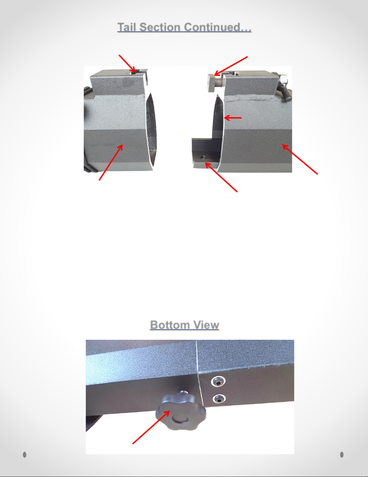
While lowering the T-Bolt from the Tail Section into the T-Bolt Slot on top of
the Main or other section, slide the Connecting Tongue from the adjoining Tail
or other extension section toward the Main Section, aligning screw holes.
Insert the Mounting Knob through the aligned holes in the bottom of the Main
Boom Section. Then tighten the Mounting Knob. Repeat this process for
remaining Boom Sections.
Note: Proper assembly is achieved when the edges of the Sections are flush.
Mounting Knob 8
Connecting Tongue
Tail Section Continued…
Main Boom Section or Tail
Extension Section
Tail Section
T-Bolt
T-Bolt Slot
Edges flush
when tight

9
Tail Section Continued…
Note : This page only applies to 2000 Series Cranes.
1. Place the end of the Turnbuckle that has the R mark, toward the Tail
Section. (This will allow all of the Turnbuckles to tighten and loosen in
the same direction.)
2. Insert Turnbuckle Pins through the Turnbuckle and Eyelet, then install the
Quick Release Clip. Repeat this process for the other side of
Turnbuckle.
3. Finally hand tighten the Turnbuckle. (Only hand tighten turnbuckles).
Tighten them inwards, drawing the boom sections toward each other.
4. Repeat this process for remaining boom sections.
Turnbuckle Pin
Quick
Release
Clip
Turnbuckle Eyelet
Tail Section
Main Section
Side View
Top View
R
Tighten inward Tighten inward
L
This manual suits for next models
1
Table of contents
Popular Camera Accessories manuals by other brands

Viltrox
Viltrox EF-NEX Mount instructions

Calumet
Calumet 7100 Series CK7114 operating instructions

Ropox
Ropox 4Single Series User manual and installation instructions

Cambo
Cambo Wide DS Digital Series Main operating instructions

Samsung
Samsung SHG-120 Specification sheet

Ryobi
Ryobi BPL-1820 Owner's operating manual