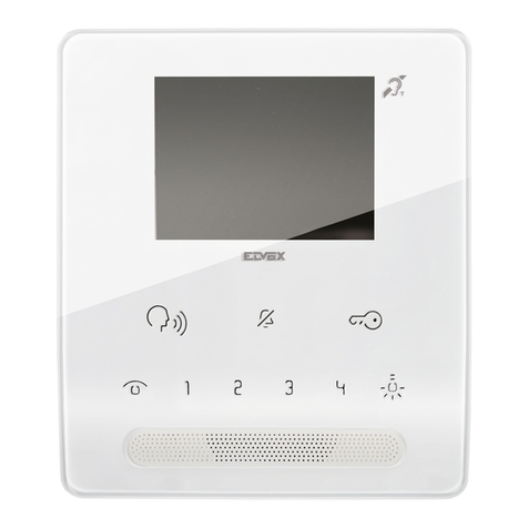
Byron DIC-24122 User manual

DIC-24122

2

DIC-24122
en • 15/07/2019

Table of Contents Byron
iv
Table of Contents
1 Safety ..........................................................................................................................................................................................................6
1.1 Installation Safety...............................................................................................................................................................................6
1.2 Operation Safety ................................................................................................................................................................................6
2 Parts description .......................................................................................................................................................................................6
2.1 What's in the box................................................................................................................................................................................6
2.2 Indoor unit (monitor)...........................................................................................................................................................................6
2.3 Outdoor unit (doorbell) .......................................................................................................................................................................7
3 Installation..................................................................................................................................................................................................7
3.1 Fix the mounting plate of the indoor unit (monitor) ............................................................................................................................7
3.2 Fix the mounting plate of the outdoor unit (doorbell) .........................................................................................................................7
3.3 Electrical installation ..........................................................................................................................................................................7
3.3.1 Connecting the terminal blocks (Indoor and Outdoor unit) ................................................................................................. 7
3.3.2 Mount the indoor units and outdoor unit ............................................................................................................................. 8
3.3.3 Connecting an additional monitor (not included)................................................................................................................. 8
3.3.4 Connecting the AC power ................................................................................................................................................... 8
3.3.5 Connecting a door lock (not included) ................................................................................................................................ 8
3.3.6 Connecting a gate opener (not included)............................................................................................................................ 9
4 Replace call button....................................................................................................................................................................................9
5 Basic functions ..........................................................................................................................................................................................9

Byron Table of Contents
v
5.1 Answering a call.................................................................................................................................................................................9
6 Home screen and menus ..........................................................................................................................................................................9
6.1 Monitor menu .....................................................................................................................................................................................9
6.2 Internal intercom ..............................................................................................................................................................................10
6.3 Recording playback menu ...............................................................................................................................................................10
6.4 Photo menu......................................................................................................................................................................................10
6.5 Settings menu ..................................................................................................................................................................................10
6.5.1 Select photos or video recordings..................................................................................................................................... 10
6.5.2 Video duration................................................................................................................................................................... 10
6.5.3 Number of photos ............................................................................................................................................................. 11
6.5.4 Image settings................................................................................................................................................................... 11
6.5.5 Customer service information ........................................................................................................................................... 11
6.5.6 Formatting MicroSD card\Internal memory ....................................................................................................................... 11
6.5.7 Date and time settings ...................................................................................................................................................... 11
6.5.8 Ringtone and volume ........................................................................................................................................................ 11
7 Frequently asked questions ...................................................................................................................................................................11
8 Specifications ..........................................................................................................................................................................................12
9 Environment.............................................................................................................................................................................................13
10 Declaration of Conformity.......................................................................................................................................................................13

Instruction manual
6
1 Safety
1. Please read these instructions carefully before installing and
using the product.
2. Do not cut the power supply cable to extend it; the device
(transformer) will not work with a longer cable. Do not plug in the
device until all the wiring has been finished.
1.1 INSTALLATION SAFETY
1. Keep children and bystanders away while installing the products.
Distractions can cause you to lose control.
2. Do not overreach when installing this product. Keep proper
footing and balance at all times. This enables better control in
unexpected situations.
3. This product is not a toy. Mount it out of reach of children.
1.2 OPERATION SAFETY
1. Do not operate electrically powered products in explosive
atmospheres, such as in the presence of flammable liquids ,
gases, or dust. Electrically powered products create sparks which
may ignite the dust or fumes.
2. The warnings, precautions, and instructions discussed in this
instruction manual cannot cover all possible conditions and
situations that may occur. It must be understood by the operator
that common sense and caution are factors which cannot be built
into this product, but must be supplied by the operator.
3. Do not expose the Power Adapter of this product to rain or wet
conditions. Water entering the Power Adapter will increase the
risk of electric shock.
4. Do not abuse the Power Cord. Never use the cord for unplugging
the plug from the outlet. Keep cord away from heat, oil, sharp
edges or moving parts. Damaged or entangled cords increase the
risk of electric shock.
5. The adapter must match the outlet. Never modify the plug in any
way. Unmodified plugs and matching outlets will reduce risk of
electric shock.
2 Parts description
2.1 WHAT'S IN THE BOX
1. Indoor unit (monitor)
2. Outdoor unit (doorbell)
3. Mounting plate outdoor unit (doorbell)
4. Mounting plates monitors
5. AC adapter
6. Additional call button for outdoor unit
7. Cables
8. Terminal blocks
9. Instruction manual
10. Screws and plugs
2.2 INDOOR UNIT (MONITOR)
1. Microphone
2. Home button

Instruction manual
7
3. Touchscreen
4. MicroSD card slot
2.3 OUTDOOR UNIT (DOORBELL)
1. Microphone
2. Camera
3. Speaker
4. Call button (replaceable, extra button included)
5. Call button 2 (replaceable, extra button included)
6. Lock release time switch (On the back of the unit)
3 Installation
3.1 FIX THE MOUNTING PLATE OF THE
INDOOR UNIT (MONITOR)
To mount the monitor, you will need the following tools:
üA suitable screwdriver for the included screws.
üA drill and suitable drill bit for the included screw plugs.
A. Position the provided mounting plate where desired.
B. Mark the screw positions with a pen.
C. Drill the necessary holes.
D. Insert the plugs.
E. Pull the required cables through the mounting plate.
F. Fasten the mounting plate with the screws.
G. Repeat steps a-f for the second monitor.
3.2 FIX THE MOUNTING PLATE OF THE
OUTDOOR UNIT (DOORBELL)
To mount the outdoor unit, you will need the following tools:
üA suitable screwdriver for the included screws.
üA drill and suitable drill bit for the included screw plugs.
A. Position the provided mounting plate where desired.
B. Mark the screw positions with a pen.
C. Drill the necessary holes.
D. Insert the plugs.
E. Use a knife or sharp object to puncture the cable gland.
F. Pull the required cables through the cable gland.
G. Fasten the mounting plate with the screws.
3.3 ELECTRICAL INSTALLATION
3.3.1 Connecting the terminal blocks (Indoor
and Outdoor unit)
There are three terminal blocks included. The GREEN (outdoor unit)
and ORANGE (AC power) terminal blocks are always required. In
case you wish to connect an additional monitor a BLUE terminal
block is also available.
To connect the terminal blocks, you will need the following tool:
üA small flat head screw driver.
A. GREEN terminal block: Loosen the terminal screws.
B. With the terminal facing you, insert the black wire on the left and
the red wire on the right.
EN

Instruction manual
8
C. Fasten the terminal screws.
D. Connect the terminal block(s) to the indoor unit (monitor).
E. Loosen the terminal screws on the outdoor unit (doorbell). (See
sticker on the outdoor unit.)
F. Insert the wires coming from the GREEN terminal block into the
screw terminal on the outdoor unit (doorbell). Indoor unit (Monitor)
1 or 2.
G. Repeat steps a-f to connect the second monitor.
3.3.2 Mount the indoor units and outdoor unit
üA suitable screwdriver for the included screws.
A. Attach the indoor units and outdoor unit to the mounting plates.
B. Fasten the screw at the bottom of the outdoor unit.
3.3.3 Connecting an additional monitor (not
included)
In case you wish to connect an additional monitor to an existing
monitor, a BLUE terminal block is available. This monitor acts as a
repeater to one of the main monitors.
To connect the terminal blocks, you will need the following tool:
üA small flat head screw driver.
A. BLUE terminal block: Loosen the terminal screws.
B. With the terminal facing you, insert the black wire on the left and
the red wire on the right.
C. Fasten the terminal screws.
D. Connect the terminal block to the monitor. (See sticker on the
monitor for position)
E. Repeat steps a-d to fasten an identical terminal block to the other
end of the cable and connecting it to the additional monitor.
3.3.4 Connecting the AC power
To connect the AC terminal blocks, you will need the following tool:
üA small flat head screw driver.
A. ORANGE terminal block: Loosen the terminal screws.
B. With the terminal facing you: Insert the (-) wire on the left and the
(+) wire on the right.
C. Fasten the terminal screws.
D. Connect the terminal block(s) to the monitor.
3.3.5 Connecting a door lock (not included)
It is possible to connect a lock to the outdoor unit that can be opened,
using the monitor. Door locks are sold separately. Article no: DB5005
& DB5005L
To connect the door lock, you will need the following tool:
üA small flat head screw driver.
A. On the outdoor unit: Loosen the terminal screws. (see sticker on
the outdoor unit for position)
B. Insert the wires (any order)
C. Fasten the terminal screws.
D. Set the lock release time by setting switch no 1 on the doorbell.
This will set whether the lock will open for 1 or 4-7 seconds after
opening the lock on the monitor.

Instruction manual
9
E. On the lock: Loosen the 2 terminal screws. (See the manual
provided with your door lock.)
F. Insert the wires (any order)
G. Fasten the terminal screws.
3.3.6 Connecting a gate opener (not included)
It is possible to connect a gate opener to the outdoor unit that can be
opened using the monitor.
To connect the gate opener, you will need the following tool:
üA small flat head screw driver.
A. On the outdoor unit: Loosen the terminal screws. (see sticker on
the outdoor unit for position)
B. Insert the wires. (see sticker on the outdoor unit for position)
ðIt is important that the + and – wires are in the correct position.
A. Fasten the terminal screws.
B. On the gate opener: (See the manual provided with your gate
opener.)
4 Replace call button
An extra call button is added to the box. This button is marked with a
bell symbol to avoid confusion on where to push.
The original call button (without marking) on the outdoor unit is
replaceable.
Pull the call button with force to remove it.
You can use the blank button for engraving your name.
5 Basic functions
5.1 ANSWERING A CALL
When the doorbell rings, you can:
A. Press the gate button to open the gate (optional).
B. Press the lock button to open the door (optional).
C. Press the camera button to make a video or take a picture.
D. Press the talk button to talk to your visitor.
6 Home screen and menus
• Press the home button on the monitor to open the home screen.
The screen will turn on, and you can view the home screen.
The home screen allows you to access the following menus:
1. Time/date
2. Monitor menu
3. Intercom menu
4. Playback recordings menu
5. Photo menu
6. Settings menu
7. Power off
6.1 MONITOR MENU
üOpen the monitor menu from the home screen to check the live
footage from the doorbell camera.
A. Press the gate icon to open your gate.
EN

Instruction manual
10
B. Press the lock icon to open your lock.
C. Press the photo icon to take a snap shot.
D. Press the speaker icon to communicate.
ðPress the home button to exit the menu and go back to the home
screen.
6.2 INTERNAL INTERCOM
üYou need an additional monitor to use this function.
A. Open the intercom menu from the home screen on one of your
monitors.
ðThe other monitor will start chiming.
B. Press the answer icon in the top corner of the screen of the
second monitor to accept the call.
ðYou will now be able to talk to another person from one
monitor to the other.
C. Press the end call icon in the top corner on one of the monitors to
end the call.
6.3 RECORDING PLAYBACK MENU
üYou have made recordings.
A. Open the playback menu from the homescreen.
B. Use the onscreen arrow buttons to scroll through your recordings.
C. Use the onscreen controls to review or delete your recorded
footage.
6.4 PHOTO MENU
You have taken photos
A. Open the photo menu from the home screen.
B. Use the onscreen arrow buttons to scroll through your saved
photos.
C. Use the onscreen controls to review or delete your saved photos.
6.5 SETTINGS MENU
A. Select photos or video recordings
B. Video duration
C. Number of photos
D. Image settings
E. Customer service information
F. Formatting MicroSD card / Internal memory
G. Date and time settings
H. Ringtone and volume settings
6.5.1 Select photos or video recordings
You can choose if your intercom takes photos or video recordings of
your visitors.
üMake sure to have a MicroSD card installed if selecting video
recording.
A. Tap on the video icon to select video recordings
B. Tap on the photo icon to select photos.
6.5.2 Video duration
You can select video recording duration. The video starts recording
when the doorbell is activated.
üVideo must be selected in the settings menu.
A. Press the button with the desired duration, 5-30 seconds.
Table of contents
Languages:
Other Byron Intercom System manuals

Byron
Byron DIC-24112 User manual

Byron
Byron BY206 User manual

Byron
Byron DIC-23312 User manual

Byron
Byron DIC-22815 User manual

Byron
Byron DIC-24212 User manual

Byron
Byron DIC-25312 User manual
Byron
Byron BY101 User manual

Byron
Byron DIC-24312 User manual

Byron
Byron DIC-24712 User manual

Byron
Byron MP001 Instruction manual

Byron
Byron SX304 User manual

Byron
Byron DIC-24102 User manual

Byron
Byron DIC-25712 User manual

Byron
Byron 765 User manual

Byron
Byron DIC-22815 User manual

Byron
Byron DIC-24712 User manual

Byron
Byron DIC-24615 User manual

Byron
Byron W255 User manual

Byron
Byron DIC-24112 User manual

Byron
Byron DIC-24512 User manual