Body Craft SCT400g User manual

SCT400g
Seated Elliptical Trainer
CONGRATULATIONS! And THANK YOU for selecting the
BODYCRAFT SCT400g Seated Elliptical Trainer! Your choice
reflects a wise investment in you and your family’s health
and wellness. We hope you use it for many healthy years!
For your safety and benefit, please read this entire manual. Please keep the manual in a
convenient place for quick reference when needed.
Bodycraft offers a complete array of high quality fitness equipment. Please refer to our web
site at www.bodycraft.com to view more ways to enhance your lifestyle.
Your Bodycraft SCT400g has all the quality and design elements to make your workout
extremely efficient and comfortable. Your new Seated Elliptical Trainer is a serious
cardio fitness machine that will keep you motivated, challenged and within reach of your
fitness goals. The Bodycraft S CT400g will provide an efficient, low impact cardiovascular
workout that will help improve energy levels and your quality of life.
Cardiovascular training is
vital for all ages and the Bodycraft SCT400g will provide an effective workout, producing
results that will encourage you to reach your fitness goals and maintain the body you
have always wanted. Spending 15 to 30 minutes a day, three times a week is all you
need to start seeing the benefits of a regular exercise program.
As a premium exercise equipment manufacturer we are committed to your complete
satisfaction. If you have questions, suggestions or find missing or damaged parts, we
guarantee your complete satisfaction through our authorized dealer network or by contacting
us directly. Please call your local dealer or Bodycraft.
Phone: 8009905556 9am - 5pm EST Email: [email protected]
Recreation Supply, Inc.
7699 Green Meadows Dr.
Lewis Center, OH 43035
Purchaser’s Reference Information:
IT IS IMPERATIVE THAT YOU FILL IN
THE FOLLOWING INFORMATION AND
REFER TO IT SHOULD THE NEED FOR
SERVICE ARISE.
Product Name: SCT400g Elliptical Cross Trainer
Serial Number: SC _ _ _ _ _ _ _ _ _ _ _ _
Proof of purchase must be supplied to validate warranty and the product must have
been registered with Bodycraft via online at www.bodycraft.com or by calling 800990-
5556 or 7409652442 M-F 9 a.m. 5 p.m. EST.
Serial #

Product Safety ………………………….…………………………….. 1
Parts Drawing & Contents………………………………...………….. 2
Hardware & Tools …………………………………………………… 3
Assembly ……………………………………………….…………….. 4
Troubleshooting & Adjustment ……………………………..…… 9
Stretching ……………………………………………………………... 11
Computer Operation…………………………………………………... 12
Part List ………………………………………………..…………….. 18
Exploded View ……………………………………….……………… 20
Warranty ……………………………………………………………... 23
TABLE OF CONTENTS

Product Safety
1
Basic precautions should always be followed, including the following safety
instructions when using this equipment:
Read all instructions before using this equipment.
1. It is recommended that you perform warm up exercises before using this equipment.
2. Please make sure all components are not damaged and in working order before use.
3. This equipment should be placed on a flat surface while in use. Using a mat or other
material on the ground is recommended.
4. Pleasewearproperclothesandshoeswhenusingthisequipment;donotwearclothes
that might catch in any part of the equipment.
5. Do not attempt any maintenance or adjustments other than those described in this
manual. Should any problems arise, discontinue use and consult an Authorized Ser
vice Representative.
6. Use caution when stepping on and off the machine. During the workout it is
recommended that you always hold onto the stationary or upper body handle bars. To
ensure the pedals run smoothly, you may need to push or pull on the upper body
handlebars first, then follow with the leg motion.
7. Do not use the equipment outdoors.
8. This equipment is for household or light commercial use only.
9. Only one person should be on the equipment while in use.
10. Keep children and pets away from the product while in use. This machine is designed
for adults only. If you feel any chest pains, nausea, dizziness, or shortness of breath,
you should stop exercising immediately and consult your physician before continuing.
11. If you feel chest pains, nausea, dizziness, or shortness of breath, you should stop ex
ercising immediately and consult your physician before continuing.
12. The maximum weight capacity for this product is 300 lbs /135 kgs.
WARNING: Before beginning any exercise program consult your physician.
This is especially important for the persons who are over 35 years
of age or who have preexisting health problems. Read all
instructions before using any fitness equipment.
CAUTION: Read all instructions carefully before operating this product.
Retain this Owner’s Manual for future reference.

2
Part Drawing & Contents
A01 1Set A04 1Set A05 1Set A06 1Set A12/A13 1Set
Main Frame Backrest Tube Rear Stabilizer Front Stabilizer Handrail L/R
A07 1Set C10 1PC D01 1PC C07 2PC C08 2PC
Saddle Frame Upholstered,
Backrest
Computer Foot Pedal Cushion Pad
C21/C22 2Set C14/C15 1Set C35/C36 2Set C23 1PC
Handrail Arm
Decorative Cover
A/B
Upright Post
Decorative Cover
Upright Joint
Cover
L/R
Water Bottle
Holder

3
Hardware & Tools
B05 4PC B06 4PC B08 5PC B07 4PC B29 10PC
Hexagon Head
Bolt M8x16mm
Bolt M8x50mm Nylon Nut M8 Curve Washer
M8x20x1.5T
Screw M5x16mm
B26 8PC B50 4PC B53 8PC B52 4PC B57 1PC
Screw
M6*15 mm
Screw
5/16”*15mm
Washer
5/16”*16*1.5t
Screw
M8*16 mm
Washer
5/16”x30x2.0T
B61 1PC
Bolt M8x100mm
B11 8PC
Screw
3/16*18mm
1PC 1PC 1PC
Hex Tool with Phillips Screwdriver
(13/14/15mm)
Allen Key (M5) Allen Key (M6)

4
Assembly
1. PREPARATION
1.1 Open the top carton and remove the style foam block and the Upper Handrail Tube L/R
(A12/A13) to the ground.
1.2 Move the Elliptical Cross Trainer away from the carton.
1.3 The assembly steps will required 2 persons.
2. FRONT STABILIZER TUBE INSTALLATION
2.1 Use the Style Foam Block or a block of Wood to lift up the front of Main Frame (A01).
2.2 Remove Two 3/8” Screws (B24) and Four Washers 3/8” (B25) and Two 3/8" Dome Nuts
(B21) from the Main Frame (A01).
2.3 Assemble the Front Stabilizer Tube (A06) under the bracket of Main Frame (A01) with
Two 3/8” Bolts (B24), Four 3/8" Washers (B25) and Two 3/8" Dome Nuts (B21) which
were removed from step .2.2
[Tighten bolts and nuts with the Hex
Tool with Phillips Screw Driver provided.]
3. REAR STABILIZER TUBE INSTALLATION
3.1 Use the Style Foam Block or a block of Wood to lift up the rear of Main Frame (A01).
3.2 Remove Two 3/8” Screws (B24) and Two Washers 3/8” (B25) from the Main Frame (A01).
3.3 Assemble the Rear Stabilizer Tube (A05) at rear of Main Frame (A01) with Two 3/8”
Bolts (B24), Two 3/8" Washers (B25) which were removed from step .3.2
[Tighten bolts and nuts with the Hex Tool with Phillips Screw Driver provided.]
A12
A13
B21
B25
B24
B25
A01
A06
B25
B24
A05
A01

5
Assembly
4. UPRIGHT POST INSTALLATION
4.1 Lift up the Upright Post (A02) and connect the Cable I (D17 and D07) from Upright Post to the
Cable II (D18 and D08) from Main Frame (A01). then slide the extra length of cables into opening
hole of Main Frame (A01)
4.2 Slide the wires into the opening hole of Main Frame (A01) carefully and use Four M8 Screws
(B05) by fingers first for aligning the punched holes and threaded holes.
[Tighten screws with the Hex Tool with Phillips Screw Driver provided.]
Attention: Do not pinch cables.
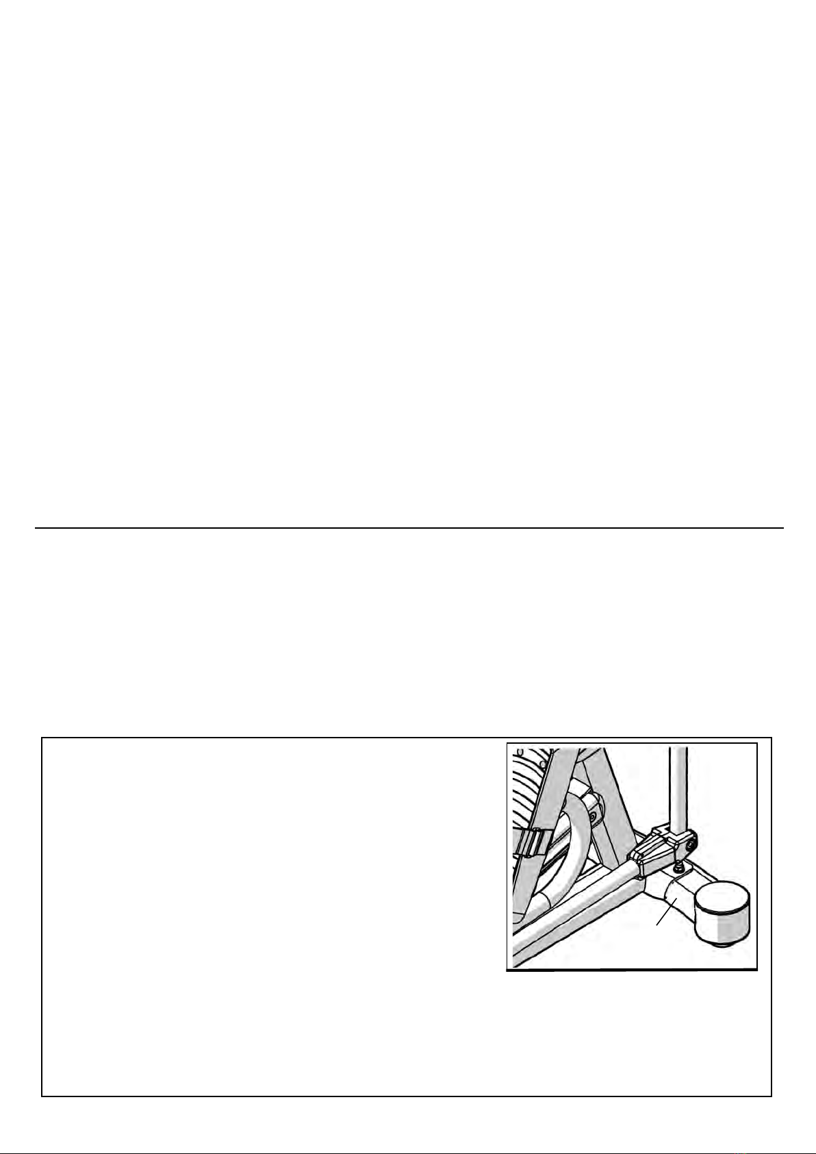
5. ADJUSTING THE ADJUSTABLE FOOT PADS
5.1 Adjust the Adjustable Foot Pads (C05) on the Main Frame (A01) as needed to level the Seated
elliptical trainer
5.2 The Seated elliptical trainer has to be leveled to prevent from wobble or shaking during the
exercise.
[Tighten screws with the Hex Tool with Phillips Screw Driver provided.]
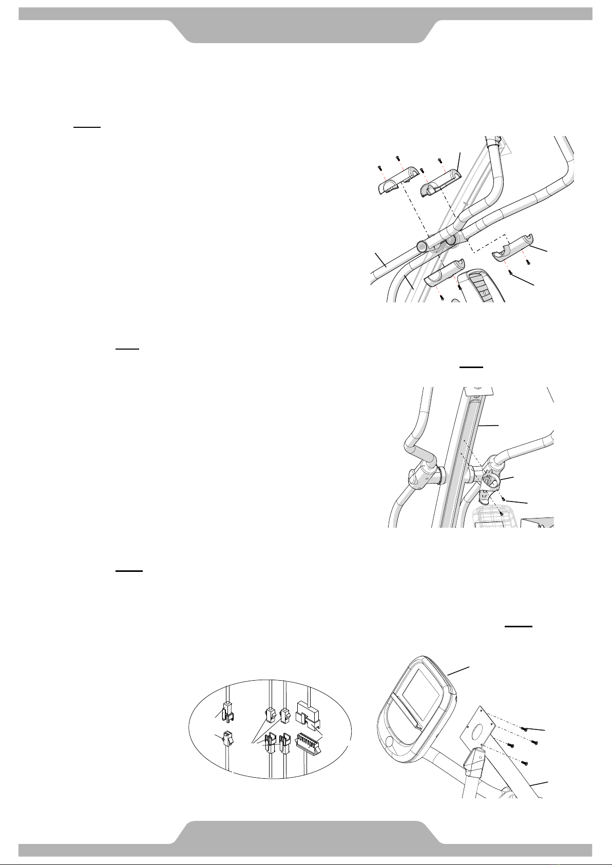
6. UPPER HANDRAIL TUBE INSTALLATION
6.1 Assemble the Upper Handrail Tube (A12/A13) into the Handrail Arm (A08/A09) with Two M8
Bolts (B06), Two M8 Curve Washers (B07) and Two M8 Nylon Nuts (B08).
6.2 Refer above step to assemble left side part..
6.3 Connect all connectors (D05/D06) from L/R Upper Handrail (A12/A13) to the matching
connectors (D10/D11) from Handrail Arm (A08/A09)
[Tighten screws with the Hex Tool with Phillips Screwdriver provided.]
Attention: Do not pinch cables.
C05
A01
B05
D06
D11
D05
D10
A13
A12
A08 A09
B06
B07
B08

6
Assembly
7. UPRIGHT JOINT COVER INSTALLATION
7.1 Assemble the Left and Right Upright Joint Covers (C15/C14) onto the brackets of Upright
Post (A02) and the Main Frame (A01) with 2 Screws M5 (B29).
[Tighten screws with the Hex Tool with Phillips Screwdriver provided.]
8. FOOT PEDAL INSTALLATION
8.1 Assemble Right Foot Pedal [C07] on Foot Pedal Tube [A17] with 4 Screws M6 [B26]. 8.2
Peel off the plastic cover of the foam tape under the Cushion Pad [C08] and attach the Cushion
Pad [C08] on Foot Pedal [C07].
8.3 Repeat the same step to assemble the Left Foot Pedal [C07]
[Tighten screws with the Hex Tool with Phillips Screwdriver provided.]
9. PIVOT CAPS INSTALLATION
9.1 Assemble the Left/Right Pivot Caps -A/B (C35/C36) onto the Right Handrail Arm (A15) with
Four M5 Screws (B11).
9.2 Repeat the same step to assemble the Pivot Caps of Right Lower Handlebar (A14).
[Tighten screws with the Hex Tool with Phillips Screwdriver provided.]
C15
C14
B29
A02
B26
C07
A17
C36
C36
C35
C35
B11
A14
C08
7
Assembly
10. PIVOT COVER INSTALLATION
10.1 Assemble the Pivot Covers A/B (C21/C22) to the pivot of Right Lower Handlebar (A09) with
Four M5 Screws (B29).
10.2 Repeat the same step to assemble the pivot covers of the left side.
[Tighten screws with the Hex Tool with Phillips Screwdriver provided.]
Attention: Do not pinch cables.
11. WATER BOTTLE HOLDER INSTALLATION
11.1 Remove Two M5 Screws (B31) from the Upright Post (A02).
11.2 Assemble the Water Bottle Holder (C23) onto the Upright Post (A02) with Two M5 Screws (B31)
which were removed from step 11.1.
[Remove/Tighten screws with the Hex Tool with Phillips Screwdriver provided.]
12. COMPUTER INSTALLATION
12.1 Remove Four M5 Screws (B16) from the bottom of Computer (D01).
12.2 Connect the Hand Pulse Cable (D07) and L/R Quick Key Cables (D10/D11) to all cables that
come from the Computer (D01).
12.3 Assemble the Computer (D01) onto the plate of Stationary Handlebar (A02) with Four M5
Screws (B16) which were removed from step 12.1.
[Remove/Tighten screws with the Hex Tool with Phillips Screwdriver provided.]
Attention: Do not pinch cables.
A08 C22
B29
A09
C21
A02
B31
C23
B16
D01
A02
D07
D10
D11
D17
Table of contents
Other Body Craft Elliptical Trainer manuals


Popular Elliptical Trainer manuals by other brands


Bonn Germany
Bonn Germany Concept 2.2 user manual

Precor
Precor Resolute RSL 620 Assembly guide

NordicTrack
NordicTrack E 9.2 Elliptical HASZNALATI UTASITAS

Vision Fitness
Vision Fitness X6600iNetTV Assembly guide

Matrix
Matrix MX-A5x owner's manual

SportsArt Fitness
SportsArt Fitness ECO-NATURAL Elite E874 owner's manual


