Body Champ BRB 5288 User manual

BRB 5288
MAGNETIC
RECUMBENT
BIKE
OWNER’S MANUAL
* This item is for consumer use only and it is not meant for commercial use.

This page intentionally left blank
Page 1
BRB 5288
General Information
Warranty
Body Flex Sports warrants your product for
a period of 1 year for the frame and 90 days
on all parts if the item is used for the intended
purpose, properly maintained and not used
commercially. Any alterations or incorrect
assembly of the product will void this warranty.
Proof of purchase must be presented for any
warranty validation (no exceptions). This
warranty applies to the original purchaser only
and is not transferable.
This warranty does not cover abuse or defects
caused during use, storage or assembly.
During the warranty period, Body Flex Sports
reserves the right to:
a). provide replacement parts to the
purchaser in an effort to repair the item.
b). repair the product returned to our
warehouse (at the purchaser’s cost).
c). replace the product if neither of the two
previously mentioned actions effect repair.
This warranty does not cover normal wear and
tear on upholstery.
Questions
If you have any questions concerning the
assembly of your item or if any parts are
missing, please DO NOT RETURN THE
ITEM TO THE STORE OR CONTACT THE
RETAILER. Our dedicated customer service
staff can help you with any questions you may
have regarding the assembly of this unit and
can also mail you replacement parts.
Customer Support
Customer Support is open 9:00 a.m. to 5:00
p.m. (Pacific Time) Monday through Friday.
Please contact us by any of the following
means.
Body Flex Sports, Inc.
21717 Ferrero Parkway, Walnut, CA 91789
Telephone: (888) 266 - 6789
Fax: (909) 598 - 6707
Email: info@bodyflexsports.com
Safety
Before you undertake any exercise program,
please be sure to consult with your doctor.
Frequent strenuous exercise should be
approved by your doctor and proper use
of your product is essential. Excessive or incorrect
training may result to health injuries. Please read
this manual carefully before commencing the
assembly of your product or starting to exercise.
• Please keep all children away from this item
when in use. Do not allow children to climb or
play on them when they are not in use.
• Supervise teenagers while they use this unit.
• For your own safety, always ensure that there
is at least 3 feet of free space in all directions
around your product while you are exercising.
• Regularly check to see that all nuts, bolts and
fittings are securely tightened. Periodically
check all moving parts for obvious signs of
wear or damage.
• Clean only with a damp cloth, do not use
solvent cleaners. If you are in any doubt, do
not use your product; contact CUSTOMER
SUPPORT.
• Before use, always ensure that your product
is positioned on a solid, flat surface. If
necessary, use a rubber mat underneath to
reduce the possibility of slipping.
• Always wear appropriate clothing and
footwear such as training shoes when
exercising. Do not wear loose clothing that
could become caught in moving parts during
exercise.
• Do not use this unit if it is not functioning
properly or if it is not fully assembled.
• Do not use this unit for commercial purposes.
This unit is for home use only.
Storage and Use
Your product is intended for use in clean
dry conditions. You should avoid storage in
excessively cold or damp places as this may
lead to corrosion and other related problems.
Weight Limit
Your product is suitable for users weighing:
300 pounds or less.
• Before use, you must read and understand all
instructions & warnings stated in this Owner’s
Manual as well as posted on the equipment.
• It is the facility owner’s responsibility to properly
instruct users on the proper operation of the
equipment and to warn them of the potential
hazards.
• If at any time during exercise you feel faint, dizzy
or experience pain, stop and consult your
physician.
Assembling Tools
- Ruler with both metric and English measurements
- 2 x Adjustable Wrenches
- 1 x Philips (”Crosshead”) Screw Driver
•
Any adjustment devices that could interfere with
the user's movement on this unit should not be
left projecting.
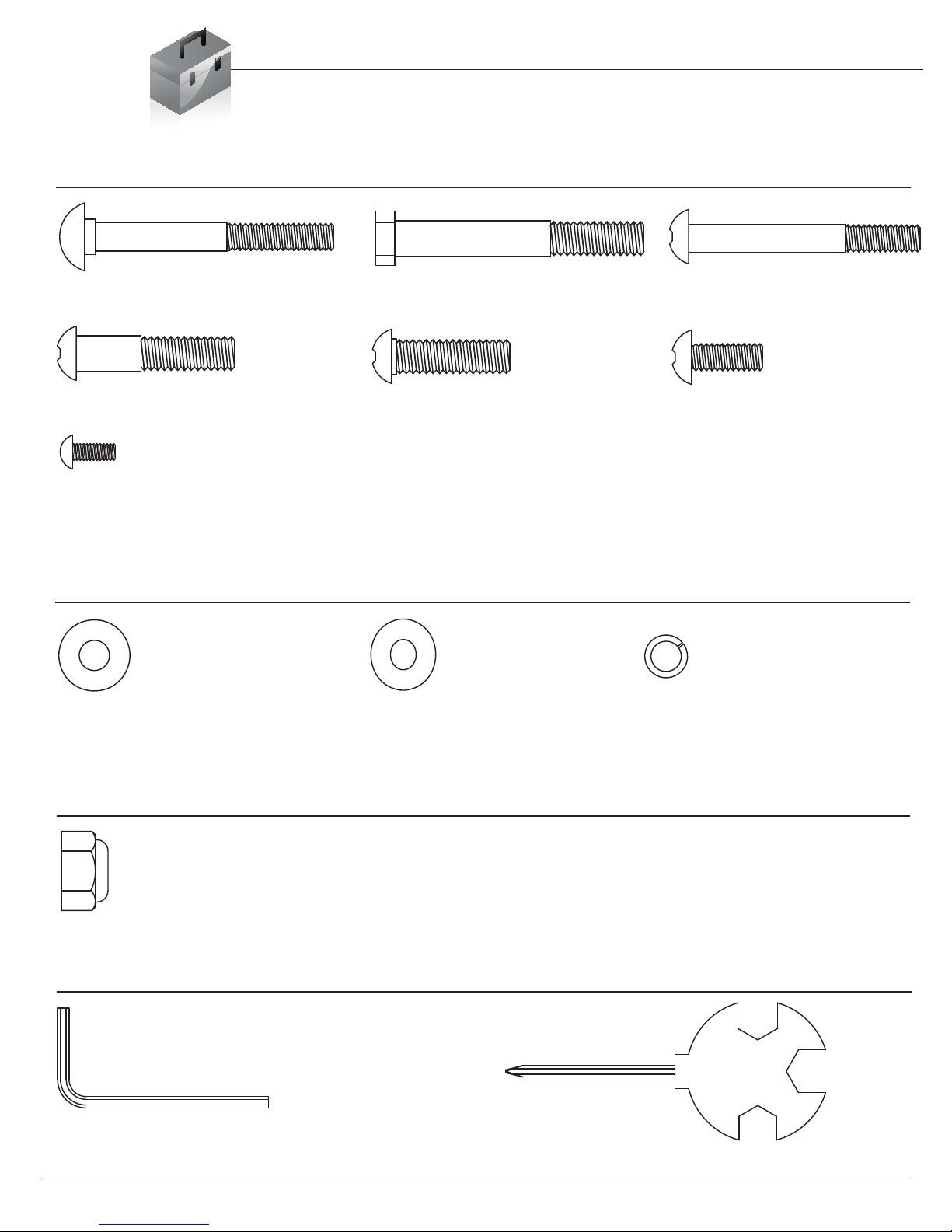
Hardware & Tool List
The following hardware is used to assemble your unit. Please take a moment to familiarize yourself with these
items. Please note some of this hardware is already pre-assembled on the machine. Do not be alarmed if you
see parts on this page that are not included in your hardware packet
#46. Wrench 1 (5 mm)
[1 piece]
#47. Wrench 2
[2 pieces]
Bolt
#37. Nut (M8) [8 pieces]
Tool
Page 2
#23. Carriage Bolt (M8x65 mm)
[4 pieces]
#25. Screw (M8x65 mm)
[2 pieces]
#26. Screw (M8x45 mm)
[2 pieces]
#24. Hex Bolt (M8x80 mm)
[2 pieces]
#30. Screw (M5x12 mm)
[4 pieces]
Washer
#28. Screw (M8x15mm)
[7 pieces]
Pre-assembled [3 pieces]
#27. Screw (M8x35 mm)
#34. Washer (M8)
[6 pieces]
#35. Arc Washer (M8)
[11 pieces]
Pre-assembled [3 pieces]
#33. Spring Washer (M8)
[3 pieces]
Pre-assembled
Nut
[1 piece]
Pre-assembled
BRB 5288
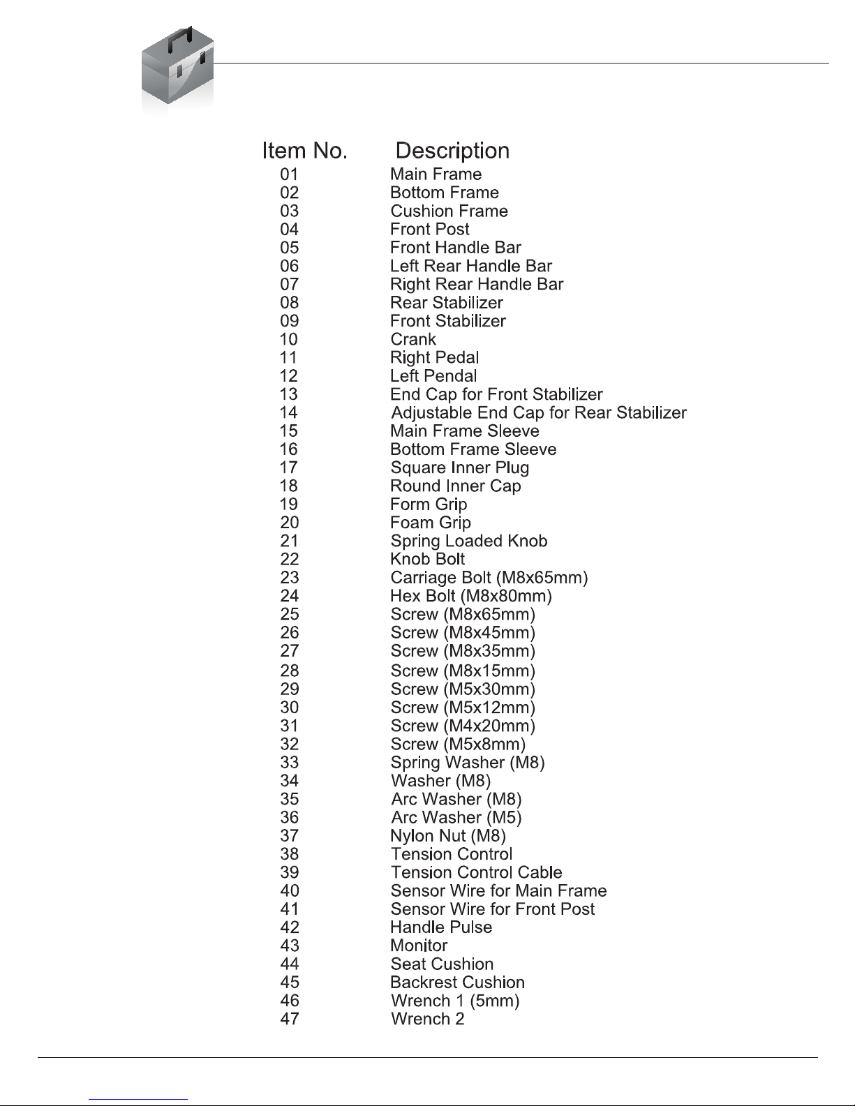
Parts Listing
The following parts list describes all of the parts illustrated on the
exploded diagram on the following page. Please note, most of
these parts are already pre-assembled on your unit.
BRB 5288 Page 3
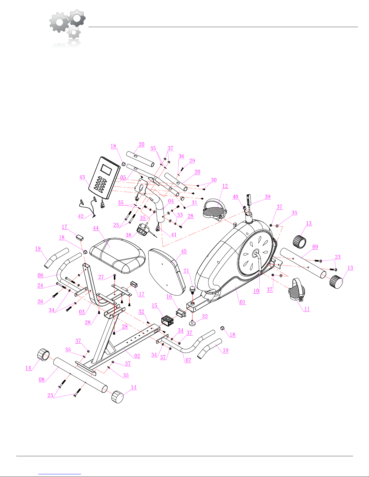
Exploded Diagram
The following diagram is provided to help you familiarize yourself with the parts and
hardware that will be used during the assembly process. Please note that not all of the
parts and hardware you see here will be used while you are assembling the machine
because some of these items are already pre-installed. Please continue to the next
page to begin the assembly process and use this page only as a reference guide for
parts and hardware.
Page 4
BRB 5288
Assembly Instructions
BRB 5288
A s s e m b l y S t e p 1
Page 5
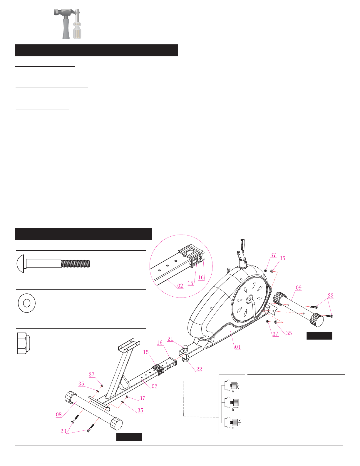
H a r d w a r e R e q u i r e d
#23. Carriage Bolt (M8x65 mm) [4 pieces]
Washer
REAR
FRONT
Spring Loaded Knob Operation
Turn knob counter-clockwise three times.
Pull knob outward and adjust bottom frame
simultaneously.
Push knob back inward until it clicks and then
tighten it by turning clockwise.
Bolt
#37. Nut (M8) [4 pieces]
#35. Arc Washer (M8) [4 pieces]
Nut
A.) Stabilizer Assembly
Attach the Front Stabilizer (#09) to the Main Frame (#01) using two Carriage Bolts (#23), two Arc Washers (#35), and two
Nuts (#37). Please note, the Front Stabilizer (#09) is the one with end caps that spin.
B.) Bottom Frame Assembly
Attach the Rear Stabilizer (#08) to the Bottom Frame (#02) using two Carriage Bolts (#23), two Arc Washers (#35), and two
Nuts (#37).
C.) Frame Assembly
Slide Main Frame Sleeve (#15) to meet the Bottom Frame Sleeve (#16) at the edge of Bottom Frame (#02) as illustrated in
the exploded diagram below. (The oval-shaped prongs of the Main Frame Sleeve (#15) should align with the oval holes on
the Bottom Frame (#02)).
Next, with the help of an assistant:
1. Loosen the Spring Loaded Knob (#21), pulling upward and
2. Simultaneously press the oval-shaped prongs on each side inward.
3. Insert the tip of Bottom Frame (#02), Main Frame Sleeve (#15), and Bottom Frame Sleeve (#16) a minimum of four inches
into the rectangular tube of Main Frame (#01) to engage the closest hole setting on the Bottom Frame (#02) for now. You can
make adjustments for seat distance after complete assembly.
4. Release the Spring Loaded Knob (#21) ensuring it is engaged with the closest hole and hand-tighten. (The small circular nubs
of the Main Frame Sleeve (#15) should now be engaged into the holes at the tip of the Bottom Frame (#02)).
The Spring Loaded Knob (#21) has a safety feature that allows you to loosen it by turning it counter-clockwise and then pull
upward (to allow for adjusting). Adjust the seat distance and then release the knob back, making sure it engages through a hole
on the Bottom Frame (#02). Tighten the knob by turning clockwise. For the user’s safety, always ensure the Spring Knob (#21)
is properly engaged through a hole on the Bottom Frame (#02).
(Note: For users shorter in height, slide the Bottom Frame (#02) further into the Main Frame (#01), and farther out for taller users.)

A s s e m b l y S t e p 2
Page 6
Hardware Required
Bolt
#37. Nut (M8) [2 pieces]
#24. Hex Bolt (M8x80 mm)
[2 pieces]
Washer
#27. Screw (M8x35 mm)
#34. Washer (M8)
[4 pieces]
Nut
[1 piece]
A.) Seat Cushion Frame Assembly
Attach the Cushion Frame (#03) to the slot on the Bottom
Frame (#02) as illustrated using one Screw (#27).
B.) Handlebar Assembly
On the left side, attach the Left Rear Handlebar (#06) to the
Bottom Frame (#02) and Cushion Frame (#03) by inserting
through two Hex Bolts (#24) in two Washers (#34) so that the
Hex Bolts (#24) are fully engaged through the right side.
On the right side, attach the Right Rear Handlebar (#07) onto
the protruding ends of the Hex Bolt (#24) and secure the
composition together using two Washers (#34) followed by two
Nuts (#37).
BRB 5288
Assembly Instructions
Assembly Step 3
Page 7
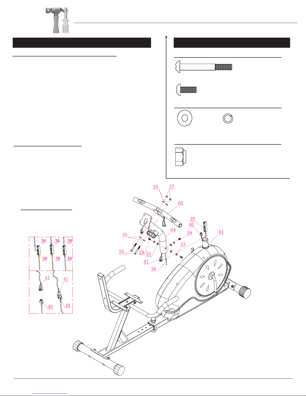
Hardware Required
Bolt
#37. Nut (M8) [2 pieces]
#25. Screw (M8x65 mm)
[2 pieces]
Washer
#28. Screw (M8x15mm)
[3 pieces]
#35. Arc Washer (M8)
[7 pieces]
#33. Spring Washer (M8)
[3 pieces]
Nut
BRB 5288
A.) Sensor Wire Connection & Tube Assembly
Remove the pre-assembled parts from Front Post (#04) and set
them aside nearby: Three Screws (#28), three Spring Washers
(#33), and three Arc Washers (#35).
With the help of an assistant, connect Tension Control (#38) to
Tension Control Cable (#39) as shown in exploded diagram A,
and Sensor Wire for Front Post (#41) to Sensor Wire for Main
Frame (#40) as shown in the exploded diagram B.
Then, being careful to tuck the connected wires into the hollow
tubing to avoid pinching/damaging the wires, slide Front Post (#04)
onto the protruding tube of Main Frame (#01). Secure using a total
of three Screws (#28), three Spring Washers (#33), and three Arc
Washers (#35) that were set side nearby.
B.) Front Handle Bar Assembly
Attach the Front Handle Bar (#05) to the front of the Front Post
(#04) by inserting two Screws (#25) through two Arc Washers
(#35) up through the Front Post (#04) and secure together using
two Arc Washers (#35) and two Nuts (#37).
A
B
Assembly Instructions
TENSION WIRE ASSEMBLY
Insert the tip of the Tension
Control (38) wire into the Tension
Control Cable (39) head at an angle.
Tilt the Tension control (38) wire
into the crevice and then pull upward.
Assembly Step 4
Page 8
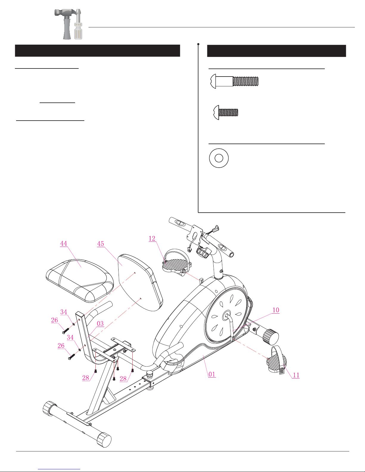
Hardware Required
Bolt
#26. Screw (M8x45 mm)
[2 pieces]
Washer
#28. Screw (M8x15mm)
[4 pieces]
#34. Washer (M8)
[2 pieces]
BRB 5288
A.) Pedal Assembly
Screw on the Right Pedal (#11) to the Right Crank
(#10) by turning the Right Pedal (#11) clockwise.
Repeat on the other side using Left Pedal (#12) and
turning COUNTER-clockwise.
B.) Cushion Assembly
Attach the Backrest Cushion (#45) to the vertical
portion of the Cushion Frame (#03) and secure using
two Screws (#26) and two Washers (#34).
Then, attach the Seat Cushion (#44) to the horizontal
base of the Cushion Frame (#03) by inserting up four
Screws (#28) to secure.
Assembly Instructions
Table of contents
Other Body Champ Exercise Bike manuals

Body Champ
Body Champ BRB 5007 User manual

Body Champ
Body Champ BF 718 User manual

Body Champ
Body Champ BRB835 User manual

Body Champ
Body Champ BRM 3600 User manual

Body Champ
Body Champ BF 620 User manual

Body Champ
Body Champ BRM 6110 User manual

Body Champ
Body Champ BRB 5328 User manual

Body Champ
Body Champ BF 2700 User manual

Body Champ
Body Champ XRB 100 User manual

Body Champ
Body Champ EASY BODY RIDER CT601 User manual


 Service manual")


