
AVGear AVG-UHS24 User manual

AVG-UHS24
Features
◼Supports HDMI 2.0 and video
resolutions up to 4K@60Hz 4:4:4.
◼HDMI inputs support HDCP 2.2 and
the outputs support HDCP1.4.
◼Supports video resolution down-
scaling, the 4K@60Hz input can be
automatically downscaled to 1080P
output for compatibility with a1080P
display.
◼18Gbps high bandwidth.
◼Features RCA (L/R) jack and Toslink
connector for de-embedded audio.
◼Advanced EDID management: multiple
presets and user defined options.
◼Built-in equalizer for signal
enhancement to avoid signal
attenuation in transmission.
◼Supports CEC control to turn the
displays on/off and adjust their volume.
◼LED indicators display the operating
status.
◼Firmware update via Micro-USB port.
The AVG-UHS24 is an ultra thin 2x4 switcher splitter
with two HDMI inputs and four HDMI outputs. This
switcher splitter supports HDMI video resolutions up
to 4K@60Hz 4:4:4, 1080P and multichannel audio.
There are multiple built-in EDID settings or it will use
the EDID from the display. The switcher will de-
embed digital stereo audio to provide an analog audio
source for an existing audio system.

AVG-UHS24
PLEASE READ THIS PRODUCT MANUAL CAREFULLY
BEFORE USING THIS PRODUCT.
This manual is only for operational instruction only,
and is not to be used in a maintenance capacity. The
functions described in this version are current as of
July 2018. Any changes of functions and operational
parameters will be updated in future manual versions.
Please refer to your dealer for the latest product
details.
Version 1.0 3/7/18

AVG-UHS24
SAFETY OPERATION GUIDE
In order to guarantee the reliable operation of the equipment and safety of the
user, please abide by the following procedures in installation, use and
maintenance:
1. The system must be earthed properly. Please do not use two blade plugs
and ensure the AC power supply ranges from 100v to 240v and from 50Hz
to 60Hz.
2. Do not install the switcher in an environment where it will be exposed to
extreme hot or cold temperatures.
3. This unit will generate heat during operation, please ensure that you allow
adequate ventilation to ensure reliable operation.
4. Please disconnect the unit from mains power if it will be left unused for a
long time.
5. Please DO NOT try to open the casing of the equipment, DO NOT attempt to
repair the unit. Opening the unit will void the warranty. There are high
voltage components in the unit and attempting to repair the unit could result
in serious injury.
6. Do not allow the unit to come into contact with any liquid as that could result
in personal injury and product failure.

AVG-UHS24
TABLE OF CONTENTS
Introduction .............................................................................................................1
Introduction to the AVG-UHS24 ...................................................................1.1
Features ......................................................................................................1.2
What’s in the Box .........................................................................................1.3
Panel Description of the AVG-UHS24.....................................................................2
Front Panel ..................................................................................................2.1
Rear Panel ...................................................................................................2.2
System Connection .................................................................................................3
Usage Precautions ......................................................................................3.1
System Diagram...........................................................................................3.2
System Application.......................................................................................3.3
EDID Management ...................................................................................................4
Firmware Upgrade ...................................................................................................5
Specifications ..........................................................................................................6
Panel Drawing ..........................................................................................................7
Troubleshooting & Maintenance.............................................................................8

AVG-UHS24
1. Introduction
1.1 Introduction to the AVG-UHS24
The AVG-UHS24 is an ultra thin 2x4 switcher splitter with two HDMI inputs and four
HDMI outputs. This unit supports HDMI video resolutions up to 4K@60Hz 4:4:4,
1080P and multichannel audio. There are multiple built-in EDID settings or it will use
the EDID from the display. The switcher will de-embed digital stereo audio to provide
an analog audio source for an existing audio system.
CEC technology can be used to turn on/off the displays and adjust volume by using
the control buttons on the front panel.
1.2 Features
◼Supports HDMI 2.0 and video resolutions up to 4K@60Hz 4:4:4.
◼HDMI inputs support HDCP 2.2 and the outputs support HDCP1.4.
◼Supports video resolution down-scaling, the 4K@60Hz input can be
automatically degraded to 1080P output for compatibility with 1080P display.
◼18Gbps high bandwidth.
◼Features RCA (L/R) jack and Toslink connector for de-embedded audio.
◼Advanced EDID management: multiple presets and user defined allowed.
◼Built-in equalizer for signal enhancement to avoid signal attenuation in
transmission.
◼Supports CEC control to turn the displays on/off and adjust their volume.
◼LED indicators display the operating status.
◼Firmware update via Micro-USB port.

AVG-UHS24
1.3 What’s in the Box
▪1 x AVG-UHS24 2x4 Splitter
▪2 x Mounting ears with 4 Screws
▪4 x Rubber Feet
▪1 x Power Adapter (DC 12V 1A)
▪1 x User Manual
Note: Please confirm if the product and the accessories are all included, if not,
please contact your dealer.

AVG-UHS24
2. Panel Description
2.1 Front Panel
1. POWER LED: The LED illuminates red when power is applied.
2. OUTPUT LEDs: The LED illuminates green when there is HDMI output on the
corresponding channel.
3. SOURCE Button and LEDs:
◼Press the button to switch to next source device, and then the corresponding input
LED will illuminate green.
◼Press and hold the button at least three seconds to enable automatic switching mode.
The splitter will automatically select the first available active source device starting at
HDMI input 1.
✓Upon detecting a new source device, the splitter will automatically select the new
one. When an active source device is removed, the splitter will switch to the next
available one.
✓After restarting the splitter, it will return to the last switch state.
◼Press and hold the button for at least three seconds again to exit automatic switching
mode, and the current output won’t be changed.
4. DISPLAY ON Button and LED: Press the button to turn on the displays. The LED blinks
green when you press this button.
5. DISPLAY OFF Button and LED: Press the button to turn off the displays. The LED
blinks green when you press this button.
6. VOLUME DOWN/MUTE Button: Press the button to decrease the volume of the
displays. Press and hold this button for at least three seconds to mute the displays.
7. VOLUME UP Button: Press the button to increase the volume of the displays or exit
mute mode if the displays are already muted.
8. EDID: 3-pin DIP Switch for the Extended Display Identification Data (EDID) value setting.
Please refer to the EDID Management for more details.
9. FW: Micro-USB port for firmware updates.
Note: Only displays that support CEC can be controlled by DISPLAY ON, DISPLAY OFF,
VOLUME UP and VOLUME DOWN buttons.
123456798

AVG-UHS24
2.2 Rear Panel
①INPUTS: Two type-A female HDMI input ports to connect your HDMI sources.
②OUTPUTS: Four type-A female HDMI output ports to connect your HDMI displays.
③AUDIO OUT: RCA jack for stereo analog audio output.
④SPDIF OUT: Toslink connector for digital audio output.
⑤EDID: 4-pin DIP switch for EDID setting. Please refer to the EDID Management for
more details.
⑥DC 12V: DC barrel port to connect an AC power adapter.
123456

AVG-UHS24
3. System Connection
3.1 Usage Precautions
1. The system should be installed in a clean environment with temperature and
humidity maintained to within equipment specifications.
2. All of the power switches, plugs, sockets and power cords should be insulated
and safe.
3. All the HDMI and control devices should be connected before powering on.
3.2 System Diagram
The following diagram illustrates a typical input and output connection that could be
used with the AVG-UHS24.
3.3 System Application
Robust performance for control and signal transmission makes the AVG-UHS24 ideal
for use in the custom installation industry, IT, signal monitoring, large screen
displays, conference systems, television broadcast, education, banking and security
institutions etc.
0
1
OFF
ON
IN 1
IN 2
1
3
2
4
4K Blu-ray Soundbar
STB
HDTV
Speaker
HDTV
HDMI 2.0 Tx
HDMI 2.0 Rx
HDTV
HDMI IN:
HDMI OUT:
AUDIO:
HDBaseT:
AVG-UHS24
4. EDID Management
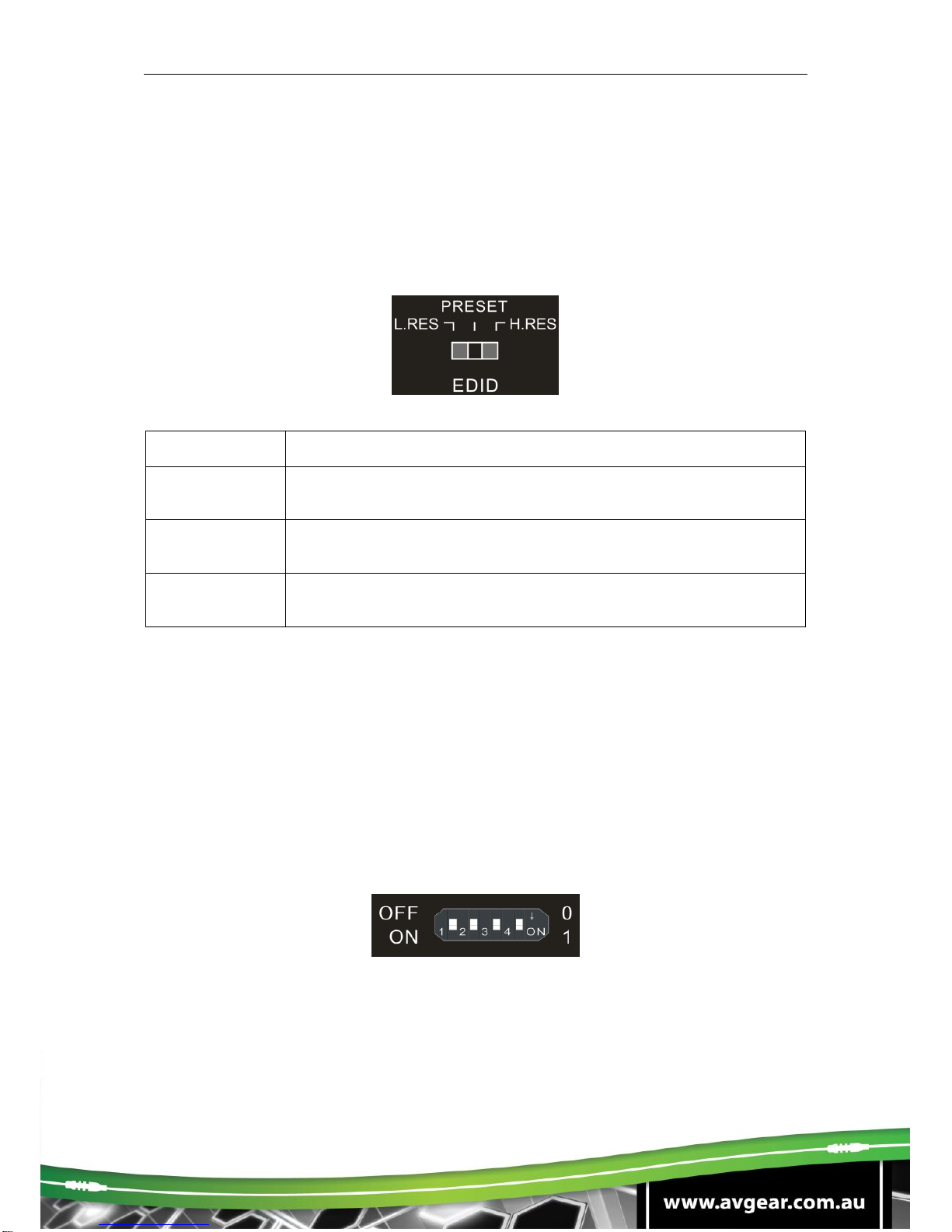
The Extended Display Identification Data (EDID) is used by the source device to match its
video resolution with the connected display. By default, the source device obtains its EDID
from the first connected display. When displays with different resolutions are connected to
the splitter, the 3-pin DIP switch on the front panel and the 4-pin DIP switch on the rear panel
can be used in combination to set the EDID to a fixed value.
Switch Status
Description
L.RES
The splitter reads all EDID information from all connected displays,
and choose the one with lowest resolution passing to the source.
PRESET
In this mode, the 4-pin DIP switch on the rear panel can be used to
select predefined EDID and customize a specific EDID as need.
H.RES
The splitter reads all EDID information from all connected displays,
and choose the one with highest resolution passing to the source.
⚫Predefined EDID setting
When the 3-pin DIP switch on the front panel is in PRESET mode, the 4-pin DIP switch on
the rear panel can be used to set the EDID to a built-in fixed value. Use the following table to
determine the settings for the 4-pin DIP switch for specific video resolution and audio
capabilities.
When in the lower position, the switch represents “1”, while putting the switch in the upper
position, it represents “0”.
Table of contents
Other AVGear Switch manuals

AVGear
AVGear AVG-UHC41A User manual

AVGear
AVGear AVG-SC121D-TN User manual

AVGear
AVGear AVG-DMM1616 User manual

AVGear
AVGear AVG-SC42T User manual

AVGear
AVGear AVG-DSS61 User manual

AVGear
AVGear AVG-HDE2 User manual

AVGear
AVGear AVG-UDA24-HD70 User manual

AVGear
AVGear AVG-SC51T User manual

AVGear
AVGear AVG-CSK-HD44 User manual

AVGear
AVGear AVG-SC51D User manual


