
APG B Series User manual

APG
R
Doc #9004258
Rev C, 04/16
LOE Ultrasonic Level Sensors
User Manual
Web Enabled Controller, Series B
www.calcert.com [email protected]1.800.544.2843 0
5
10
15
20
25
30

ii
Table of Contents
Introduction ................................................................................................................ iii
Warranty and Warranty Restrictions.................................................................... iv
Chapter 1: Specications and Options..................................................................... 1
Dimensions ........................................................................................................................................1
Specications ............................................................................................................................... 2-3
Model Number Congurator.......................................................................................................... 3
System Wiring Diagrams ........................................................................................................... 4-6
Chapter 2: Installation and Removal Procedures and Notes..............................7
Tools Needed..................................................................................................................................... 7
Connection Notes............................................................................................................................. 7
Electrical Installation ..................................................................................................................... 7
Installation Notes ............................................................................................................................ 8
Mounting Instructions ................................................................................................................... 8
Software Setup ............................................................................................................................9-13
Removal Instructions ................................................................................................................... 13
Chapter 3: Programming with Modbus TCP/IP...................................................14
Modbus Polling via Ethernet with Modbus TCP/IP...........................................................14-15
LOE Generic Modbus Register List .............................................................................................15
Modbus Programming of Individual Sensors.......................................................................... 16
Chapter 4: LOE Embedded Web Server..................................................................16
Accessing the LOE Embedded Web Server ............................................................................. 16
Navigating the LOE Embedded Web Server ........................................................................16-17
LOE Sensor Input Conguration Submenus.......................................................................18-32
Modbus Sensor Conguration Registers............................................................................ 33-35
LOE Utility Menus ................................................................................................................... 36-39
Chapter 5: Maintenance .......................................................................................... 40
General Care....................................................................................................................................40
Troubleshooting.............................................................................................................................40
Calibration ....................................................................................................................................... 41
Repair and Returns........................................................................................................................ 41
www.calcert.com [email protected]1.800.544.2843 0
5
10
15
20
25
30

iii
Introduction
Thank you for purchasing an LOE Ultrasonic Level Sensor and Web Enabled Controller from APG. We
appreciate your business! Please take a few minutes to familiarize yourself with your LOE and this manual.
The LOE Ultrasonic Level Sensor and Web Enabled Controller oers a wide degree of integrated, exible,
remote and local control and monitoring for your system. The LOE can control up to 10 APG Modbus
sensors--any combination of level, pressure, magnetostrictive and ultrasonic--and two input or output
relay terminals. All readings are available for control and monitoring via TCP/IP for local or remote network
access. The LOE also had exible power options: it can use either POE or an independent 12-28 VDC power
source.
Reading your label
Every APG controller comes with a label that includes the controller’s model number, part number, and
serial number. The LOE label also indicates the default IP address, subnet mask, and mac address. Please
ensure that the model number on your label matches your order.
www.calcert.com [email protected]1.800.544.2843 0
5
10
15
20
25
30
1
Chapter 1: Specications and Options
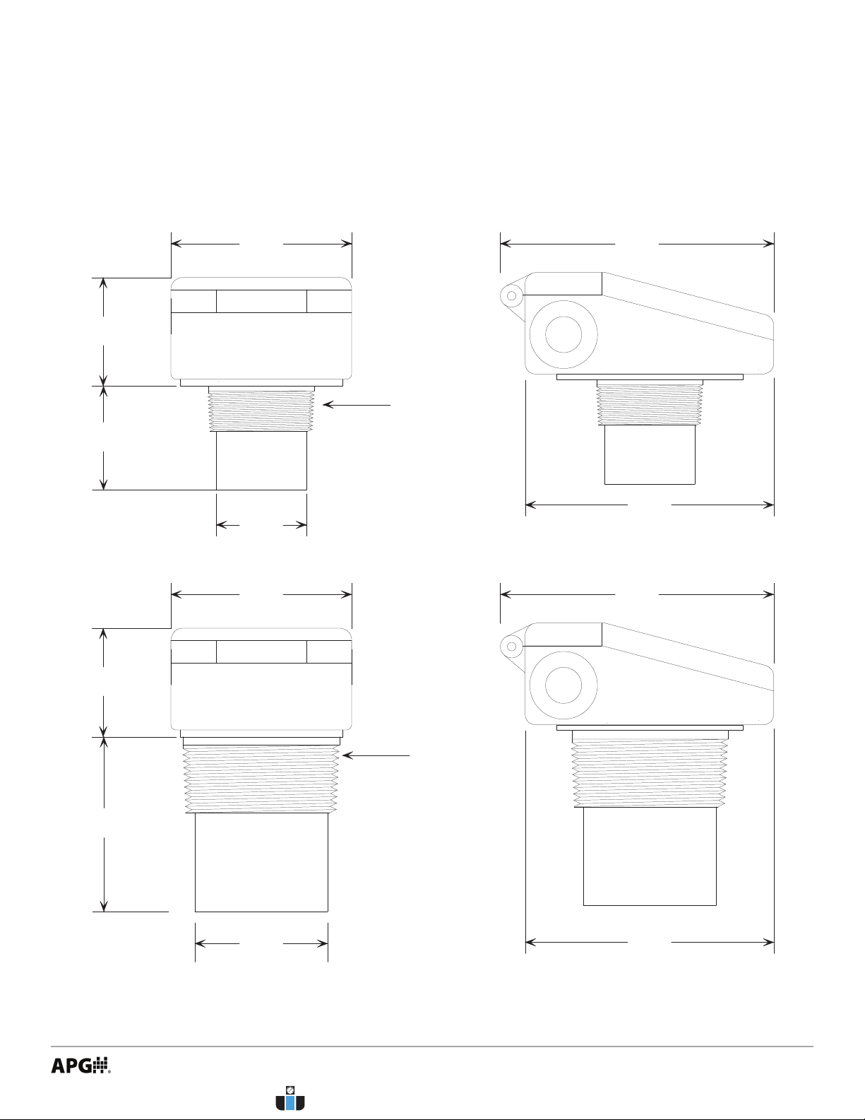
• Dimensions
6.05”
153.7mm
5.50”
139.7mm
6.05”
153.7mm
5.50”
139.7mm
3.00”
76.2mm
3” NPT
3.86”
98.0mm
2.40”
61.0mm
4.00”
101.6mm
2” NPT
2.00”
50.8mm
2.40”
61.0mm
2.30”
58.4mm
4.00”
101.6mm
LOE-2126, LOE-6126
LOE-3136
www.calcert.com [email protected]1.800.544.2843 0
5
10
15
20
25
30

2
Performance
Operating Range 0.6 - 15.0 ft. / 7 in. - 180 in. / 178mm - 4572mm (6126)
1.0 - 25.0 ft. / 12 in. - 300 in. / 305mm - 7620mm (2126)
1.5 ft. - 40 ft. / 18 in. - 480 in. / 458mm - 12192mm (3136)
Beam Pattern 9° o axis
Transducer Frequency 43 kHz (3136) / 69 kHz (2126, 6126)
Response Time Programmable, 5 Hz maximum (200 ms)
Communications
Digital Output Ethernet TCP/IP Modbus
Ethernet TCP/IP via embedded webserver (LAN only)
Ethernet TCP/IP to APG-provided website
0-2 Isolated Solid State Relays
Inputs RS-485 Modbus (up to 10 slave sensors)
0-2 Discrete Switches
Electrical
Operational Supply Voltage (at sensor) 48 VDC via POE (requires injector or switch)
12-28 VDC
Current Draw 40 mA @ 48 VDC
80 mA @ 24 VDC
Power Rating (LOE) 2.0 W Max
Isolated SS Relays 120V, 120 mA Max
Accuracy
Accuracy ±0.25% of detected range
Resolution 0.1 inch (2.54 mm)
Environmental
Operating Temperature -40 to 60°C (-40 to 140°F)
Internal Temperature Compensation Yes
Enclosure Protection IP65
Materials of Construction
Transducer Housing PVDF
Upper Housing PC/PET
Transducer Type Ceramic, PVDF faced
• Specications
www.calcert.com [email protected]1.800.544.2843 0
5
10
15
20
25
30

3
Mounting
LOE-2126 2” Ø NPT
LOE-3136 3” Ø NPT
LOE-6126 2” Ø NPT
Compatible APG Modbus Senors
Ultrasonic MNU
Magnetostrictive MPX-E1, MPX-R1
Pressure PT-400-L5, PT-400-L31, PT-500-L5, PT-500-L31
Controllers DCR-1006A, MND
• Model Number Congurator
Model Number: LOE - _____ - _____
A B
A. Model
□ 2126 1 - 25 ft. (305mm - 7620mm); 69 kHz; 2” NPT threads
□3136 1.5 - 40 ft. (458mm - 12192mm); 43 kHz; 3” NPT threads
□6126 0.6 - 15 ft. (178mm - 4572mm); 69 kHz; 2” NPT threads
B. Relay Conguration
□ 0000 2 relay outputs
□0010 1 relay output, 1 switch input
□0110 2 switch inputs
www.calcert.com [email protected]1.800.544.2843 0
5
10
15
20
25
30

4
External 12-28 VDC Source Wiring
• System Wiring Diagrams
COM
OK SEND/
RESET
24V B A GND
RS-485
24V B A GND
RS-485
To 12-28 VDC Power Supply
+
-
ETHERNET
PORT TR1 TR1 TR2 TR2 NOTE: Power terminals for 24V and
GND can only be used to power Modbus
sensors if LOE is powered via POE.
If LOE is powered via 12-28 VDC supply,
Modbus sensors must be powered
independently.
POE (Power over Ethernet) Wiring
POWER
LAN + DCLAN
To
Network
Connection
To AC
power
POE
Power
Injector
Terminal inside housing
supplies 24 Vdc to power
attached Modbus devices
when powering the LOE
from a POE source.
24V B A GND
RS-485
www.calcert.com [email protected]1.800.544.2843 0
5
10
15
20
25
30
5
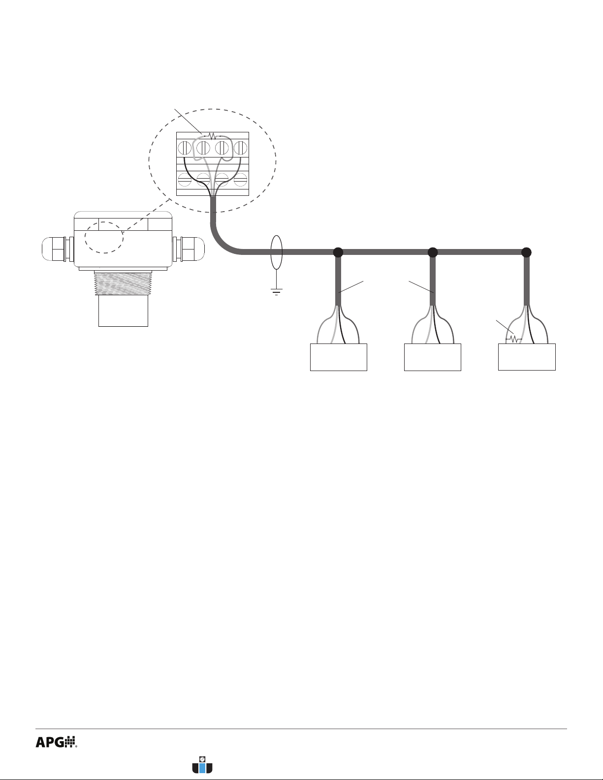
Modbus Sensor Daisy-chain Wiring
270 Ω
terminating
resistor at
last sensor
Sensor 3
V+
A
B
GND
Trunk Line
Sensor 1
V+
A
B
GND
Sensor 2
V+
A
B
GND
Use shielded cable
Sensor Line Drops
270 Ω terminating
resistor NOT internal
to LOE
Note: Terminating resistor size recommended
based on input resistance of LOE. Length
of cable and overall impedence of network may
necessitate a different size resistor.
NOTE: Power terminals for 24V and
GND can only be used to power Modbus
sensors if LOE is powered via POE.
If LOE is powered via 12-28 VDC supply,
Modbus sensors must be powered
independently.
24VBAGND
RS-485
TR1TR1TR2TR2
www.calcert.com [email protected]1.800.544.2843 0
5
10
15
20
25
30

6
System Overview - LOE with Modbus network, SSR’s and Internet Connection
Network / Internet Connection
Computer
on
Local
Network
Computer
on
Internet
MNU Ultrasonic Sensors MP Magnetostrictive Float Level Sensors
Solid State Relays
Modbus
Input
Connection to
Internet
Server Hosting
Website and
Logged Data
www.calcert.com [email protected]1.800.544.2843 0
5
10
15
20
25
30

7
Chapter 2: Installation and Removal Procedures and Notes
• Connection Notes
• Up to 10 Modbus sensors can be connected to the LOE in any combination.
• Output SSR’s are rated for 120V, 120mA max.
• Flat head screwdriver to remove knockouts for cables.
• If you are using a stand pipe to mount your LOE, you will probably need tools to install the stand pipe.
• For any attached Modbus sensors, please consult each sensor’s user manual for installation notes and
instructions.
• Tools Needed
• Use at head screwdriver to remove knockouts on either side of LOE housing.
• Insert included cable ttings in knockout holes.
• Connect any relays rst.
• Connect LOE to Ethernet/network.
• Connect independent 12-28 VDC supply if not using POE.
• Connect and set up one Modbus sensor at a time.
• Electrical Installation
IMPORTANT: Each Modbus sensor must be connected to the network individually and
assigned a unique Sensor Number before the next sensor can be added.
IMPORTANT: Multiple Modbus sensors added to the network simultaneously are all
assigned the same Modbus address/sensor number: 1. Sensors MUST be added to the
network individually.
www.calcert.com [email protected]1.800.544.2843 0
5
10
15
20
25
30
This manual suits for next models
3
Table of contents
Other APG Accessories manuals













