Alber CargoMaster A 130 User manual

Operator’s Manual
CargoMaster A 130/131
A 281
O10

1 Table of Contents
2. Introduction
3. Brief Survey
3.1 General Information
3.2 Functional Concept
3.3 Functional Sequence
3.4 Description A130
3.5 Description A131
3.6 Description A281
3.7 Description O 10
4. Before Using the CargoMaster
4.1 Checking the Safety Brakes
5. Operating the CargoMaster
5.1 Safety Instructions
5.2 Parking Without a Load
5.3 Parking With a Load
5.4 Moving on Level Ground
5.5 Adjusting the Handlebars
5.6 Picking up Loads
5.7 Loading with the Adjustable Toe Plate
5.8 Loading a Vehicle
5.9 Unloading a Vehicle
5.10 Climbing Upstairs
5.11 Climbing Downstairs
5.12 Operation in Single Step Mode
6. Accessories
6.1 Horizontal Platform
6.2 Supporting Frame (only applicable to A281)
6.3 Portable Stairs
6.4 Spare Batteries
7. Maintenance
7.1 General Information
7.2 Retightening the Chain
7.3 Exchanging the Electrical Fuses
7.4 Exchanging the Batteries
8. Lead Batteries
8.1 General Information
8.2 Charging the Lead Batteries
9. Problems and Solutions
10. Warranty and Liability
10.1 Warranty
10.2 Liability
11. Appendix
Noise and Vibrations
Declaration of CE Conformity
Note
CargoMaster
A130 GB 7/98

2 Introduction
Congratulations, you acquired a powerful and versatile ma-
chine to transport loads.
The CargoMaster will shortly be an indispensable help to you.
However, in order to transport heavy loads effortlessly up-
and downstairs, it is necessary to acquire a certain skill in
using the CargoMaster.
For this reason we ask you to read the operator’s manual
carefully and pay particular attention to all warning and sa-
fety instructions before using the CargoMaster for the first
time.
We further suggest that, in order to get used to this stair-
climbing device, you practise handling it first without loads.
For safety reasons it is mandatory to observe strictly the
maximum limit for loads.
CargoMaster
A130 GB 7/98

3 Brief Survey
3.1 General Information
Everybody who sees the CargoMaster in action for the first
time is fascinated by its climbing mechanism.
Precisely those people who are technically inclined end up
shaking their heads as they try to understand how it works.
If one did not see the CargoMaster actually climb up- and
downstairs, one would reach the conclusion that this
couldn’t possibly work, and yet it does.
3.2 The Functional Principle
The major focus lies at the axle (F) at the frame (A) of the
CargoMaster around which the lifting levers (E) together with
the big wheels (C) rotate (see 3.3 “Functional Sequence”).
The big wheels are not powered; instead they rotate freely
on the motor shaft. The small supporting wheels (B) are also
not powered but rotate freely.
The lifting levers are fixed to the motor shaft by means of
teeth. If the motor rotates, then the lifting levers inevitably
also rotate around the axis (D), which is both the axis of the
motor shaft as well as of the not powered big wheels. The
other ends of the lifting levers, as described previously, ro-
tate freely around the axis (F) attached to the frame of the
CargoMaster. This free rotation inevitably results in the clim-
bing process’ intended up or down movement of either the
big wheels or the frame of the CargoMaster on the stairs.
Depending on the constellation of the frame, lifting levers,
and big wheels to each other certain positions follow in
which one can either drive or park the CargoMaster.
How one can use the up and down movement of the big
wheels and the frame of the CargoMaster to climb stairs is
shown and described in detail as follows.
CargoMaster
A130 GB 7/98
A
B
C
D
E
F
FIGURE 1
D
F
FIGURE 2

3.3 Functional Sequence
For the purpose of describing the functional sequence, plea-
se assume that the CargoMaster is in the position “moving
on level ground.” More precisely, the moving gear and the
frame are in such a position to each other that one can easi-
ly drive on level ground. This starting position of the Cargo-
Master is called 0°. The lifting levers are in an approximately
horizontal position as shown in Figure 3. The rotating axis of
the lifting levers and the axles of the big wheels are on about
the same level.
The First Phase
Drive the CargoMaster to the first step of the stairs in the
position 0°. Push the up/down switch to “UP” and the motor
begins to rotate.
The motor shaft can rotate freely in the big wheels and, sin-
ce the lifting levers are connected with the motor shaft, the
lifting levers rotate around the axis of the big wheels, which,
in turn, inevitably lifts the frame.
The rotation moves from 0°
to 45° and at position 90°
one can see that the lifting
levers lifted the frame into
its highest possible positi-
on. The small supporting
wheels climbed along and
touch down on the next
step at approximately 135°
(see Figure 4). This conclu-
des the first phase.
The Second Phase
Once the supporting wheels touched down on the step, the
big wheels are moved up to the same step passing the posi-
tions 180° and 225° (see Figure 5).
At roughly 270° the big
wheels reach their hig-
hest possible position
and at about 315° they
take over the load of the
small supporting wheels.
In the meantime one pulls
the CargoMaster back to
the edge of the following
step. The final position
360° coincides with the
starting position 0°,
which concludes the se-
cond phase and the pro-
cess can be repeated.
CargoMaster
A130 GB 7/98
FIGURE 3
180° 225° 270° 315° 360°
FIGURE 5
45
°
0
°
90
°
135
°
FIGURE 4

3.4 Description A 130
1 = Handlebars
2 = Up/Down Switch
3 = Safety Belt
4 = Toe Plate
5 = Supporting Wheels
6 = Big Wheels
7 = Power Switch and Single
Step Switch (optional)
8 = Fuses
9 = Socket for the Recharger
10 = Fastening Lever
Technical Data: A 130
Dimensions
Height: 1120 mm
Width: 580 mm
Depth: 470 mm
Handlebars extendible up to 1770 mm
Weight (with batteries) 31 kg
Lifting Capacity 130 kg
Sealed Batteries 12 V / 10 Ah
DC Motor 12 V
Climbing Rate 13 steps per minute
Capacity with one charge of the batteries 10-15 stories, depending on the load
CargoMaster
A130 GB 7/98
1
6
2
5
4
10
5
8
7
9
3
FIGURE 6

3.5 Description A 131
1 = Handlebars
2 = Up/Down Switch
3 = Safety Belt
4 = Toe Plate
5 = Supporting Wheels
6 = Big Wheels
7 = Power Switch and Single
Step Switch (optional)
8 = Fuses
9 = Socket for the Recharger
10 = Fastening Lever
Technical Data: A 131
Dimensions
Height: 1120mm
Width: 580 mm
Depth: 470 mm
Handlebars extendible up to 1770 mm
Weight (with batteries) 32 kg
Lifting Capacity 130 kg
Sealed Batteries 12 V / 13 Ah
DC Motor 12 V
Climbing Rate 17 steps per minute
Capacity with one charge of the batteries 15-30 stories, depending on the load
CargoMaster
A130 GB 7/98
1
6
2
5
4
3
10
5
8
7
9
FIGURE 7

3.6 Description A 281
1 = Handlebars
2 = Up/Down Switch
3 = Safety Belt
4 = Adjustable Toe Plate
5 = Supporting Wheels
6 = Big Wheels
7 = Power Switch and Single
Step Switch (optional)
8 = Fuses
9 = Socket for the Recharger
10 = Fastening Screw Knob
Technical Data: A 281
Dimensions
Height: 1130mm
Width: 590 mm
Depth: 520 mm
Handlebars extendible up to 1800 mm
Weight (with batteries) 43 kg
Lifting Capacity 280 kg
Sealed Batteries 12 V / 13 Ah
DC Motor 12 V
Climbing Rate 7 steps per minute
Capacity with one charge of the batteries 15-30 stories, depending on the load
CargoMaster
A130 GB 7/98
1
6
2
5
4
3
10
5
8
7
9
FIGURE 8

3.7 Description 0 10
1 = Handlebars
2 = Safety Belt
3 = Up/Down Switch
4 = Fastening Levers
5 = Fuse 2,5 A
6 = Socket for the Recharger
7 = Fuse 30 A
8 = Big Wheels
9 = Supporting Wheels
10 = Loading Fork
Technical Data: O 10
Dimensions
Height: 890mm
Width: 610 mm
Depth: 460 mm (250 mm fork folded)
Handlebars extendible up to 1400 mm
Weight (with batteries) 26 kg
Lifting Capacity 100 kg
Sealed Batteries 12 V / 12 Ah
DC Motor 12 V
Climbing Rate 17 steps per minute
Capacity with one charge of the batteries 15-30 stories, depending on the load
CargoMaster
A130 GB 7/98
11
6
2
5
4
4
3
10
8
87
9
FIGURE 9
4 Before Operation
Before you use the CargoMaster for the first time, please
make sure the batteries are completely charged, as shown
in chapter 8.2 Charging the Lead Batteries.
+Please check the safety brakes each time before you use the CargoMaster.
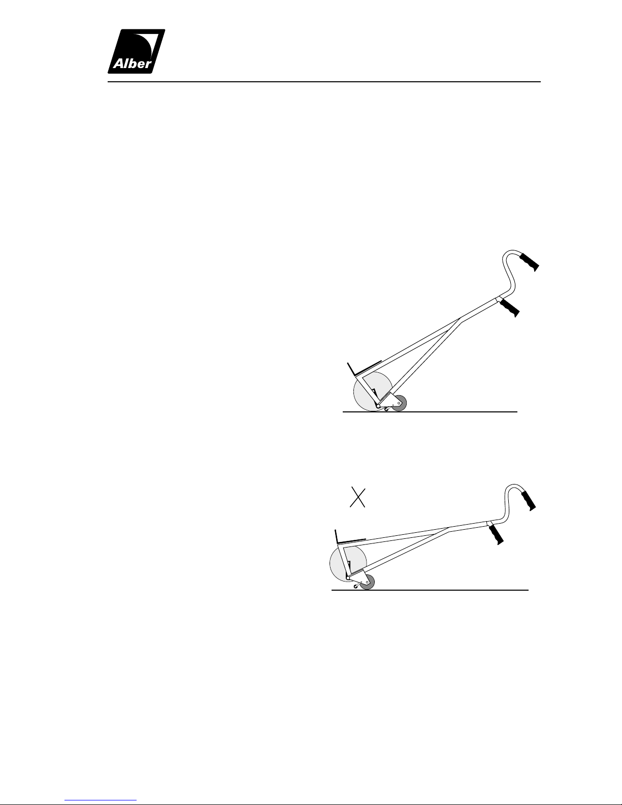
4.1 Checking the Safety Brakes
First, put the CargoMaster in the parking position
by pushing the up/down switch, as shown in Figu-
re 10.
Then, tilt the machine so far towards you
that the loading surface of the frame is al-
most in a horizontal position; this movement
lifts the big wheels off the ground, so that
only the small supporting wheels still touch
the ground. At this point the safety brakes
hinge down, engage and block the supporting
wheels as shown in Figure 11.
If the machine cannot be pushed forward, but
only rolled backward, then the braking effect
for a safe use of the CargoMaster is achieved.
+If this braking effect does not set in, the CargoMaster may not be used under any circums-
tances. Please contact your local dealer or the manufacturer immediately.
CargoMaster
A130 GB 7/98
FIGURE 10
à
à
FIGURE 11
This manual suits for next models
3
Table of contents


