Acclaim Lighting Dyna Drum SO QW User manual

www.acclaimlighting.com
User guide
Dyna Drum SO™
Dyna Drum SO QW™


1
Contents
Introduction .....................................................................2
Welcome 2
Safety 2
Supplied items 3
Optional extras 3
Installation........................................................................4
Mounting the unit 4
Fitting a snoot 5
Fitting a spread lens 5
Using an optional tenon mount 6
Power and control wiring 7
Operation..........................................................................9
Entering the menu 9
Menu navigation 9
Determining solo behavior 12
Programming and displaying a chase 12
Selecting and displaying a static color 13
Selecting and displaying a dimmed white 13
Setting the DMX address 14
Setting the keylock 14
Adjusting the user display 15
Setting a white balance 15
Further information ...................................................... 16
Troubleshooting 16
Dyna Drum SO specifications 17
Limited product warranty 18

2
Introduction
Welcome
Welcome to the Dyna Drum SO range from Acclaim Lighting. These ruggedized LED-
powered fixtures are designed to replace traditional external flood lights while using a
fraction of the power. Featuring a die-cast aluminum body throughout with full IP66 wet
location environmental rating, these fixtures are built to last.
External control using the industry standard DMX512-A is supported or you can opt to
create static or chasing color outputs internally using the intuitive user menu.
A range of spread lenses and snoots are available to widen and restrict the light output as
required so that it perfectly matches your installation.
Safety
•When fixtures are mounted off-ground, ensure that a suitably rated safety wire is used to
attach the fixture to a secure secondary point.
•Ensure that the power input is supplied from a correctly fused, earthed and
environmentally protected location.

3
Supplied items
Optional extras
Dyna Drum SO or Dyna Drum SO QW
Both variants supplied with integral mounting yoke
and 5 foot (1.5m) power/control tails.
Full snoot
Gray [DDSOFSG]
Black [DDSOFSB]
White [DDSOFSW]
Half snoot
Gray [DDSOHSG]
Black [DDSOHSB]
White [DDSOHSW]
Spread lens
20obeam [DDSSL20]
40obeam [DDSSL40]
60obeam [DDSSL60]
10ox 60obeam [DDSSL1060]
Tenon mounts
2” pole [TM2]
4” pole [TM4]

4
Installation
Mounting the unit
Each Dyna Drum SO fixture includes a sturdy yoke mount with multiple holes in its base
for various fixing options. Dyna Drum SO fixtures weigh 26.4lbs (12Kg) - ensure that the
mounting surface and the fixings used are sufficiently rated for the task (including wind
shear forces).
Safety wire
anchor hole
IMPORTANT: When mounting a Dyna
Drum SO xture o ground, ensure
that a safety wire (with a SWL rating
of at least 26.4lbs (12Kg)) links the
anchor hole at the rear of the Dyna
Drum SO with a suitably sturdy
secondary xing point.
The yoke adjusters on each side of the
Dyna Drum SO require a 5/16”(8mm)
hex key to focus the fixture.
A useful angle chart is provided on each
side to assist with initial adjustment.
Use a 5/16” or 8mm
hex key
Angle chart
When installing each Dyna Drum SO fixture, ensure that the surface
is level and that nothing is protruding to damage the mounting
yoke. The yoke has multiple mounting holes and is designed to
be surface mounted. Approved mounting surfaces include steel,
aluminum, concrete or wood structures. Bolts or screws (not
supplied) should be suitable for the surface and, together with
large washers, ensure a secure mount for the fixture.
5
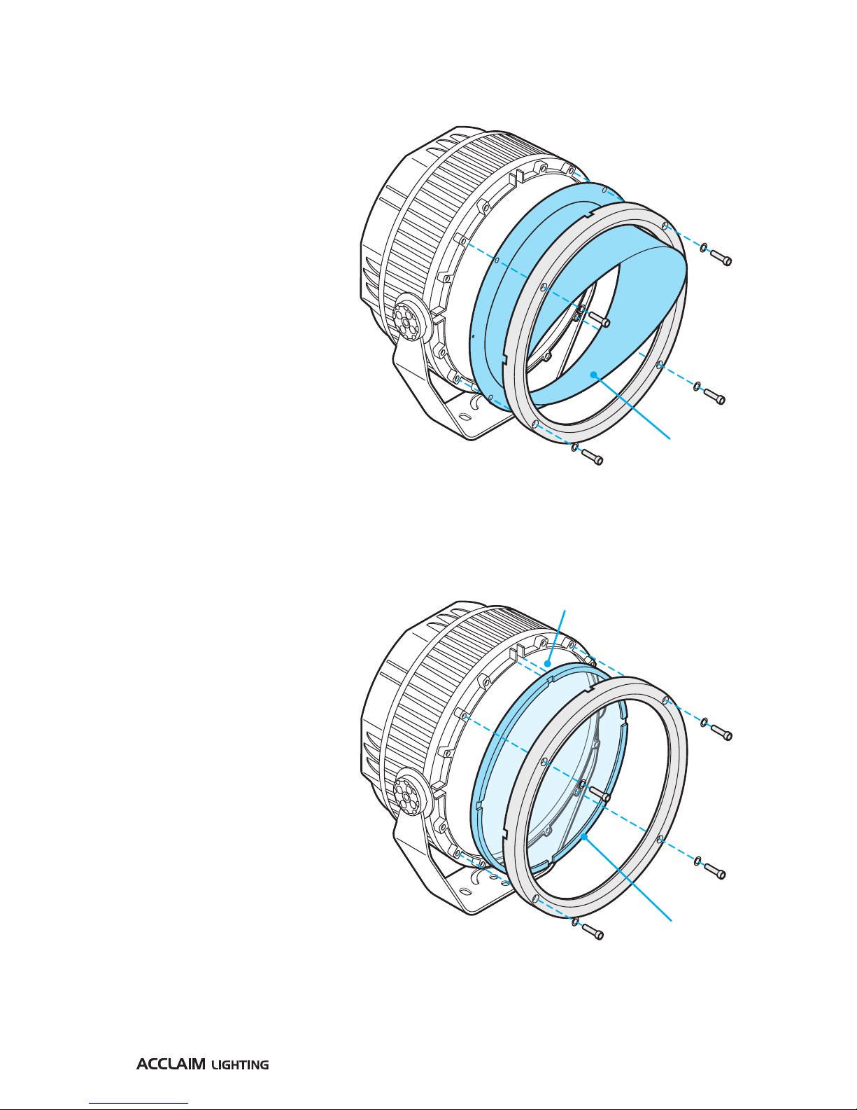
IMPORTANT: Ensure the notches are facing
outwards and are fully aligned with the
grooves of the xture’s inner ring. The
frosted side of the lens
must face inwards to
the emitters.
Fitting a snoot
Snoots help to reduce or eliminate light
spill into unwanted areas. The full and
half snoots available from Acclaim
Lighting are attached to the Dyna
Drum SO units in the same way.
1 Using a 3/16”(4mm) hex key,
remove the four bolts that
secure the front ring.
2 Remove the front ring and
place the snoot onto the
front of the fixture. The snoot
mounting holes must align with
the same threads that are used by
front ring. There are also two small
holes either side of the snoot that
must fit onto the small pins either side
of the fixture.
3 Replace the front ring and tighten the bolts evenly.
Spread lens with
rubber surround
Full or half
snoot
Fitting a spread lens
You can widen the native beam angle
using an optional spread lens.
1 Using a 3/16” (4mm) hex key,
remove the four bolts that
secure the front ring and
remove the ring.
2 Remove the protective films
on either side of the lens
and place it into the inner
ring of the emitter face. To
allow water drainage, the
four notches of the lens’ rubber
surround must face outwards
and be fully aligned with the open
grooves of the fixture’s mounting
ring (also the frosted side of the lens
must face inwards towards the emitters).
3 Replace the front ring and tighten the bolts evenly.
Note: It is possible to use both a spread lens and a snoot. Fit the lens first and then add the snoot.
Tip: Adding accessories is much easier if the Dyna Drum SO front face is pointing vertically upwards.

6
Using an optional tenon mount
Optional tenon mounts are available for use when a Dyna Drum SO needs to be mounted
on top of a vertical pole. Tenon mounts are available for use with 2” and 4” poles of sufficient
rigidity for the weight of the fixture.
IMPORTANT: Tenon mounts are
suitable only for vertical pole
mounts where the xture sits on
top of the pole. Tenon mounts
must NEVER be used to hang a
Dyna Drum SO below a pole. For
pendant-type installations, please
enquire about the Dyna Drum SO
pendant model.
To use a tenon mount
1 Slide the tenon mount onto the
vertical pole and secure using the
two bolts on the side (6mm hex key
required).
2 Fix the Dyna Drum SO to the tenon
mount using the supplied main
bolt (17mm A/F wrench required)
and pan control bolt (6mm hex key
required) as shown right.
3 Where required, feed the mains
and control cables into the access
holes and down the pole to a
suitable exit point.
4 Use a suitable silicone sealant to
cap off the cable access holes to
prevent water ingress.
Main
bolt
Pan
control
bolt
Pole
bolts

7
Power and control wiring
The power and control cords (roughly five feet, 1.5m in length) enter the casing via water-
tight glands at the rear of the fixture. As standard the cords are supplied as bare tails.
Power
The power requirements are as follows:
•Voltage: 100-277VAC 50/60Hz
•Power: 145W at steady state
The power cord color designations are as follows:
Power cord colors
US version
Power cord colors
European version
In-rush current
Although LED fixtures are low power devices compared to their incandescent equivalents,
their power supplies exhibit a trait known as ‘in-rush current’ when they are first powered
on. This is caused by the various components within the switching power supplies topping
themselves up with power. The in-rush current period lasts only milliseconds and does not
cause any effect when a handful of units are powered on at the exact same time. However,
if many fixtures are linked to the same power input, they will momentarily pull a current that
may greatly exceed their normal operating level. This may affect over-current trips when
power is applied. For this reason it is advisable to limit the number of fixtures on any one
power input.
8
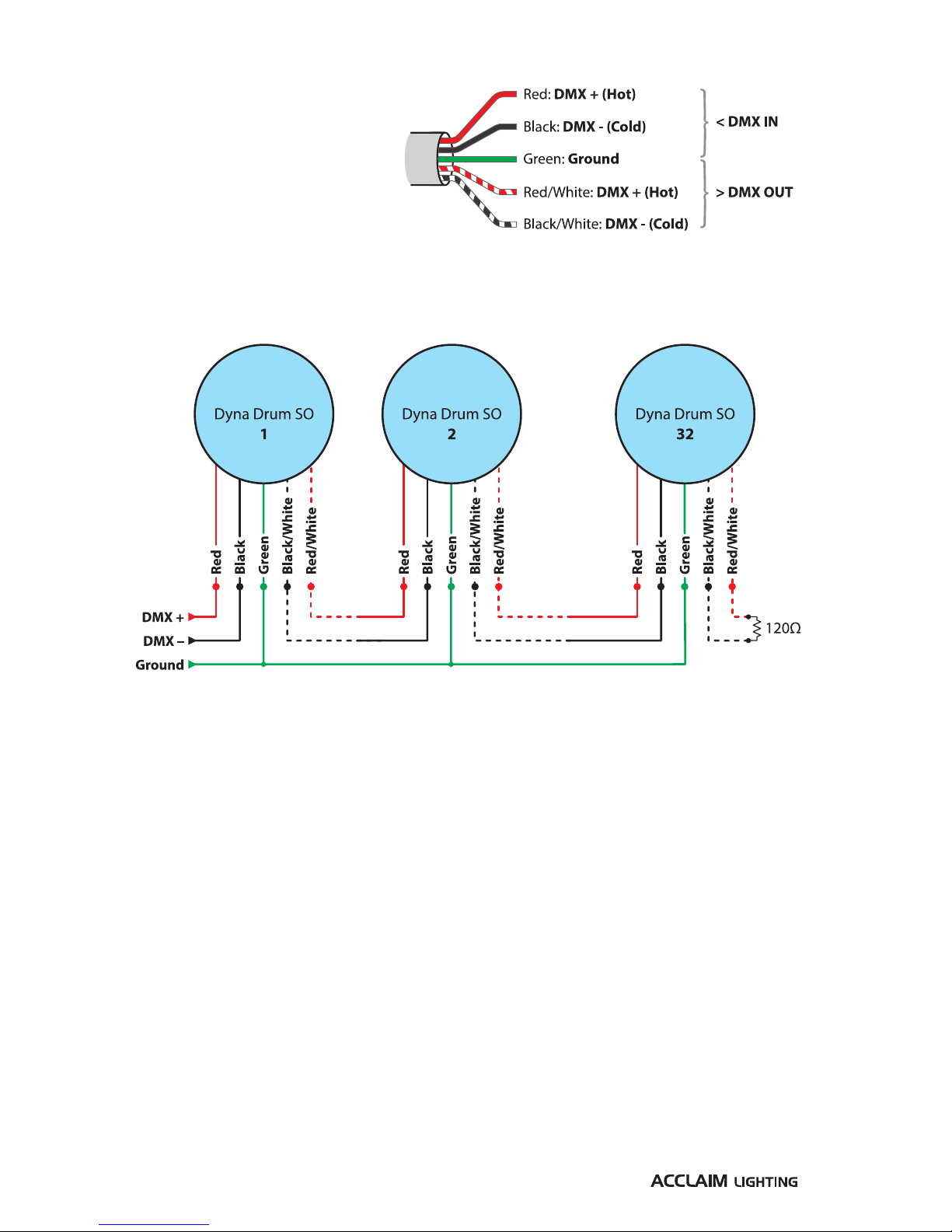
Control
The control cord has five cores
to provide DMX512-A input and
output connections:
When connecting multiple fixtures, connect the DMX control input lines to the first fixture
and feed the output of that fixture to the next. The final fixture in the line should have a
120Ω terminating resistor connected between the DMX + and DMX – lines:
Tips for achieving successful DMX control
•Do not exceed a total cable length of 3,900 ft (1200m) without buffering.
•Do not exceed a total of 32 fixtures on a single line without buffering.
•Use only connection cables with a characteristic impedance of 120Ω, preferably where
the DMX + and DMX – data lines are twisted around each other and the ground link exists
as a coaxial screen surrounding the inner cores.
•Connect a 120Ω terminating resistor between the DMX + and DMX – output connections
of the final fixture.
•Do not introduce a passive Y-split into the control cabling. If it is necessary to split the
control link in order feed fixtures located in different directions, use a powered DMX
splitter/buffer.
•Ensure that the DMX + and DMX – connections do not become crossed at any point.
This manual suits for next models
1
Table of contents
Other Acclaim Lighting Floodlight manuals

Acclaim Lighting
Acclaim Lighting RDD Manual

Acclaim Lighting
Acclaim Lighting RDA Manual

Acclaim Lighting
Acclaim Lighting ILB Manual

Acclaim Lighting
Acclaim Lighting ILA Manual

Acclaim Lighting
Acclaim Lighting REA Manual

Acclaim Lighting
Acclaim Lighting LFL2M Assembly instructions

Acclaim Lighting
Acclaim Lighting RBC Manual

Acclaim Lighting
Acclaim Lighting RBE Manual

Acclaim Lighting
Acclaim Lighting Dyna Drum HO User manual

Acclaim Lighting
Acclaim Lighting Dyna Accent User manual


