4B Watchdog Super Elite User manual
www.go4b.com/usa
Watchdog™Super Elite
BUCKET ELEVATOR & BELT CONVEYOR
HAZARD MONITORING SYSTEM
INSTALLATION INSTRUCTIONS
OPERATION MANUAL
Part No.’s - WDC4V4C, WDC4V46C
Hardware Version R4 - Software Version 4.8.X
CUS
®

1. CUSTOMER SAFETY RESPONSIBILITIES Page 6 - 7
2. PRODUCT OVERVIEW Page 8
3. SPECIFICATIONS Page 8
4. FEATURES Page 9 - 10
5. DIMENSIONS Page 11
6. INSTALLATION Page 11
7. SENSOR PLACEMENT DIAGRAMS Page 12
8. ELECTRICAL CONNECTION Page 13 -14
9. WIRING DIAGRAMS Page 15 - 25
9.1 Wiring Block Diagram for Bucket Elevator & Belt Conveyor Page 15
9.2 Control Wiring Diagram (120 - 240 VAC) Page 16
9.3 Control Wiring Diagram (24 VDC) Page 17
9.4 Control Wiring Diagram for Multiple Units Page 18 - 19
9.5 Select New Prole Page 20
9.6 WDC3 to WDC4 Sensor Wiring Diagram Page 21
9.7 Sensor Wiring Diagram Prole with Touchswitches Page 22
9.8 Sensor Wiring Diagram Prole with Rub Blocks Page 23
9.9 Sensor Wiring Diagram Prole with Motion Alignment Sensors Page 24
9.10 Sensor Wiring Diagram Prole with Knee or Idler Pulleys Page 25
10. WATCHDOG MAIN LCD SCREEN Page 26 - 32
10.1 Start Up Screen (Initial Power Up) Page 26
10.2 Main LCD Screen & Sensor LEDs Page 27
10.3 Alarm Log Button Page 28
10.4 Menu Button Page 28
10.5 System Info Button Page 28
10.6 Speed Info (1 of 9) Page 28
10.7 Head Align Info (2 of 9) Page 29
10.8 Tail Align Info (3 of 9) Page 29
10.9 HBS Info (4 of 9) Page 30
10.10 EXP1 Info (5 of 9) & EXP2 Info (6 of 9) Page 30
10.11 Aux Sensor Info (7 of 9) Page 31
10.12 System Info (8 of 9) Page 31
10.13 Network Info (9 of 9) Page 32
11. VIEW SETTINGS Page 32
12. SETUP Page 33
12.1 Password Page 33
13. RESET ENGINEERING PASSWORD Page 34
14. PROFILE Page 35 - 58
TABLE OF CONTENTS

14.1 Edit Selected Prole Page 35
14.2 Calibrate System Page 36
14.2.A - System Recalibration Page 36
14.2.B - Incorrect Calibration Page 36
14.2.C - Start Up Timer Page 36
14.3 Full System Setup Page 37
14.4 System Page 37
14.4.A - Temperature Units Page 37
14.4.B - Pre Abs Alarm Page 37
14.4.C - Negative Differential Alarm Page 37
14.4.D - Rate of Rise Start Up Delay Page 37
14.5 Speed Page 38
14.5.A -Speed Monitoring Page 38
14.5.B - Scaling Units Page 38
14.5.C - Scaling Factor Page 38
14.5.D - Speed Detection Source Page 38 - 40
14.5.E - Acceleration Monitoring Level Page 40
14.5.F - Number of Starts / Minute Page 41
14.5.G - Start Up Delay Page 41
14.5.H - Underspeed Enable Page 41
14.5.I - Underspeed Alarm Page 41
14.5.J - Severe Underspeed Page 41
14.5.K - Underspeed Alarm Delay Page 41
14.5.L - Underspeed Stop Delay Page 41
14.5.M - Overspeed Enable Page 42
14.5.N - Overspeed Page 42
14.5.O - Severe Overspeed Page 42
14.5.P - Overspeed Alarm Delay Page 42
14.5.Q - Overspeed Stop Delay Page 42
14.6 Alignment (Head) Page 43
14.6.A - Head Sensor Pair Page 43
14.6.B - Head Trigger Alarm Page 43
14.6.C - Absolute Alarm Page 43
14.6.D - Relative Alarm Source Page 44
14.6.E - Relative Alarm Page 44
14.6.F - Head: Rate of Rise Page 44
14.6.G - Head Alarm Delay Page 45
14.6.H - Head Stop Delay Page 45
TABLE OF CONTENTS

14.7 Alignment (Tail) Page 46
14.7.A - Tail Sensor Pair Page 46
14.7.B - Tail Trigger Alarm Page 36
14.7.C - Absolute Alarm Page 36
14.7.D - Relative Alarm Source Page 36
14.7.E - Relative Alarm Page 46
14.7.F - Tail: Rate of Rise Page 47
14.7.G - Tail Alarm Delay Page 47
14.7.H - Tail Stop Delay Page 47
14.8 Temperature Page 48
14.8.A - HBS Page 48
14.8.B - HBS: Absolute Alarm Page 48
14.8.C - HBS: Relative Alarm Source Page 48
14.8.D - HBS: Relative Alarm Page 49
14.8.E - HBS: Rate of Rise Page 49
14.8.F - HBS: Alarm Delay Page 49
14.8.G - HBS: Stop Delay Page 49
14.8.H - AMB Page 49
14.8.I - AMB: Absolute Alarm Page 49
14.8.J - AMB: Rate of Rise Page 50
14.8.K - AMB: Alarm Delay Page 50
14.8.L - AMB: Stop Delay Page 50
14.8.M - EXP Sensors (Expansion Boards) Page 50
14.9 Auxiliary Page 50
14.9.A - Plug Enabled Page 51
14.9.B - Plug Trigger Alarm When Page 51
14.9.C - Plug Alarm Delay Page 51
14.9.D - Plug Stop Delay Page 51
14.9.E - Pulley Enabled Page 51
14.9.F - Pulley Trigger Alarm When Page 51
14.9.G - Pulley Alarm Delay Page 51
14.9.H - Pulley Stop Delay Page 52
14.10 Expansion Boards Page 52
14.10.A - Expansion 1 & 2 Page 53
14.10.B - NTC Board Page 53
14.10.C - PLC Board Page 54
14.10.D - Analog Board (6AN) Page 54
14.10.D.1 - CLI1: Custom Label Page 54
TABLE OF CONTENTS

14.10.D.2 - CLI1: Input Range Page 54
14.10.D.3 - CLI1: Min Scaled Value Page 54
14.10.D.4 - CLI1: Max Scaled Value Page 54
14.10.D.5 - CLI1: Absolute Alarm Low (On/Off) Page 54
14.10.D.6 - CLI1: Absolute Alarm Low Page 54
14.10.D.7 - CLI1: Pre-Absolute Alarm Low (On/Off) Page 54
14.10.D.8 - CLI1: Pre-Absolute Alarm Low Page 54
14.10.D.9 - CLI1: Pre-Absolute Alarm High (On/Off) Page 54
14.10.D.10 - CLI1: Pre-Absolute Alarm High Page 54
14.10.D.11 - CLI1: Absolute Alarm High (On/Off) Page 54
14.10.D.12 - CLI1: Absolute Alarm High Page 54
14.10.D.13 - CLI1: Alarm Delay Page 55
14.10.D.14 - CLI1: Stop Delay Page 55
14.10.E - Analog Board (2AN) Page 57
14.10.F - Pt100 Board Page 57
14.11 Restore Defaults Page 58
14.12 Select New Prole Page 58
15. TEST Page 59 - 60
15.1 Alarm Relay Page 59
15.2 Alignment Page 59
15.3 Over Speed Page 59
15.4 Underspeed Page 60
15.5 Hot Bearing Sensor Page 60
16. FACTORY SETTINGS Page 60 - 61
16.1 Edit Selected Prole Page 61
16.2 Restore Defaults Page 61
16.3 Select New Prole Page 61
17. SD CARD Page 62
18. TIME & DATE Page 63
19. CHANGE PASSWORD Page 63
20. NETWORK Page 64
21. TROUBLESHOOTING GUIDE Page 65 - 66
22. APPENDIX A - WDC4 MENU TREE Page 67
23. APPENDIX B - FACTORY DEFAULT SETTINGS Page 68 - 69
24. APPENDIX C - WDC4 CONFIGURATOR SOFTWARE Page 70
25. APPENDIX D - WDC4 SOFTWARE UPDATE Page 71
26. PRODUCT WARRANTY Page 75
TABLE OF CONTENTS

PAGE 6
4B appreciates your business and is pleased you have chosen our products to meet your
needs.
Please read in its entirety and understand the literature accompanying the product before
you place the product into service. Please read the safety precautions carefully before
operating the product. With each product you purchase from 4B, there are some basic
but important safety considerations you must follow to be sure your purchase is permitted
to perform its design function and operate properly and safely, giving you many years
of reliable service. Please read and understand the Customer Safety Responsibilities
listed below. Failure to follow this safety directive and the Operation Manuals and other
material furnished or referenced, may result in serious injury or death.
SAFETY NOTICE TO OUR CUSTOMERS
A. In order to maximize efciency and safety, selecting the right equipment for each
operation is vital. The proper installation of the equipment, and regular maintenance
and inspection is equally important in continuing the proper operation and safety
of the product. The proper installation and maintenance of all our products is the
responsibility of the user unless you have asked 4B to perform these tasks.
B. All installation and wiring must be in accordance with Local and National Electrical
Codes and other standards applicable to your industry. (Please see the article
“Hazard Monitoring Equipment Selection, Installation and Maintenance” at www.
go4b.com.) The installation of the wiring should be undertaken by an experienced
and qualied professional electrician. Failure to correctly wire any product and/or
machinery can result in the product or machine failing to operate as intended, and can
defeat its design function.
C. Periodic inspection by a qualied person will help assure your 4B product is
performing properly. 4B recommends a documented inspection at least annually and
more frequently under high use conditions.
D. Please see the last page of this manual for all warranty information regarding this
product.
CUSTOMER SAFETY RESPONSIBILITIES
1. READ ALL LITERATURE PROVIDED WITH YOUR PRODUCT
Please read all user, instruction and safety manuals to ensure that you understand
your product operation and are able to safely and effectively use this product. If the
equipment is used in a manner not specied in this manual, the protection provided by
the equipment may be impaired.
2. YOU BEST UNDERSTAND YOUR NEEDS
Every customer and operation is unique, and only you best know the specic needs
and capabilities of your operation. Please call the 24-hour hotline at 309-698-5611 for
assistance with any questions about the performance of products purchased from 4B.
4B is happy to discuss product performance with you at any time.
1. CUSTOMER SAFETY RESPONSIBILITIES

PAGE 7
3. SELECT A QUALIFIED AND COMPETENT INSTALLER
Correct installation of the product is important for safety and performance. If you have
not asked 4B to perform the installation of the unit on your behalf, it is critical for the
safety of your operation and those who may perform work on your operation that you
select a qualied and competent electrical installer to undertake the installation. The
product must be installed properly to perform its designed functions. The installer should
be qualied, trained, and competent to perform the installation in accordance with Local
and National Electrical Codes, all relevant OSHA Regulations, as well as any of your
own standards and preventive maintenance requirements, and other product installation
information supplied with the product. You should be prepared to provide the installer
with all necessary installation information to assist in the installation.
4. ESTABLISH AND FOLLOW A REGULAR MAINTENANCE AND INSPECTION
SCHEDULE FOR YOUR 4B PRODUCTS
You should develop a proper maintenance and inspection program to conrm that your
system is in good working order at all times. You will be in the best position to determine
the appropriate frequency for inspection. Many different factors known to the user will
assist you in deciding the frequency of inspection. These factors may include but are not
limited to weather conditions; construction work at the facility; hours of operation; animal
or insect infestation; and the real-world experience of knowing how your employees
perform their jobs. The personnel or person you select to install, operate, maintain,
inspect or perform any work whatsoever, should be trained and qualied to perform these
important functions. Complete and accurate records of the maintenance and inspection
process should be created and retained by you at all times.
5. RETAIN AND REFER TO THE OPERATION MANUAL FOR 4B’S SUGGESTED
MAINTENANCE AND INSPECTION RECOMMENDATIONS
As all operations are different, please understand that your specic operation may require
additional adjustments in the maintenance and inspection process essential to permit
the monitoring device to perform its intended function. Retain the Operation Manual
and other important maintenance and service documents provided by 4B and have
them readily available for people servicing your 4B equipment. Should you have any
questions, please call the free 24-hour hotline number (309-698-5611).
6. SERVICE REQUEST
If you have questions or comments about the operation of your unit or require the unit to
be serviced please contact the 4B location who supplied the product or send your request
via fax (309-698-5615) or call us via our 24-hour hotline number in the USA (309-698-
5611). Please have available product part numbers, serial numbers, and approximate
date of installation. In order to assist you, after the product has been placed into service,
complete the online product registration section which is accessed via our website
www.go4b.com/usa.
2. PRODUCT OVERVIEW
The Watchdog Super Elite (WDC4) is a user-programmable, microprocessor controlled bucket elevator and
belt conveyor monitor. The control unit accepts signals from sensors for belt misalignment, belt speed &
slip, continuous bearing temperature, pulley misalignment and plug condition monitoring. The unit is able
to sound an alarm and provide shutdown control of the elevator or conveyor, and feeding system, when a
potentially hazardous condition is detected.
Microprocessors and electronics are housed in a self-contained wall mounted control unit. An LCD screen
on the front of the unit displays system status. Calibration and set-up parameters are accessed via a
password and front panel touch buttons.
The Watchdog Super Elite can also integrate into HazardMon.com ®, which is a secure cloud based hazard
monitoring solution providing status notications and data logging for bucket elevators and conveyors. Live
system status, graphs and historical data can be viewed on any web-enabled device (smartphone, tablet
PC, desktop or laptop computer). Emails can be sent to notify users whenever a change in the system’s
health is detected. An automated maintenance feature allows site operators to verify that all sensors on
the system are operational and working correctly.
WARNING
• Rotating machinery can cause serious injury or death
• Always lockout and tagout the machine prior to installation
PAGE 8
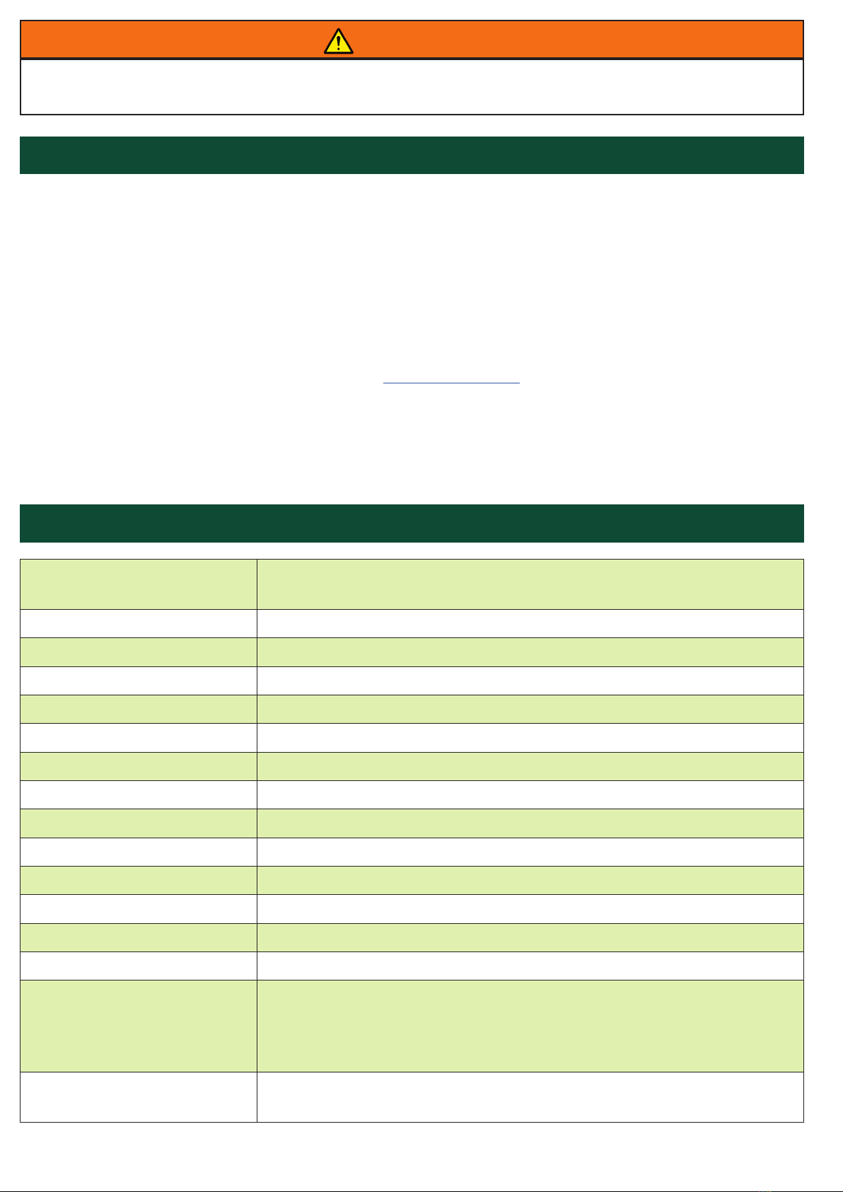
3. SPECIFICATIONS
Supply Voltage - 120 to 240 VAC or 24 VDC (WDC4V46C)
24 VDC (WDC4V4C)
Power Consumption (Max.) - 12 Watts
Power Terminals - 14 AWG / 4 mm²
Signal Terminals - 16 AWG / 2.5 mm²
Alarm Relay Contacts - 1 Pole Normally Open - 8A @ 250 VAC Voltage Free Changeover
Stop Relay Contacts - 1 Pole Normally Open - 8A @ 250 VAC Voltage Free Changeover
Sensor Supply - 24 VDC @ 800 mA (Across F1, F2 and F3)
Sensor Inputs - 15 (Expandable to 27 with Auxiliary Boards)
Interlock (Run Signal) Input - 24 VDC or 120 to 240 VAC
Dimensions (H x W x D) - 11-3/4 x 9-1/2 x 5-1/4 (inches) / 298 x 241 x 133 (mm)
Fixing Centers (H x W) - 10-7/8 x 6 (inches) / 276 x 152 (mm)
Cable Entry - 2 Holes 1-1/8 in. Diameter (28 mm)
Weight - 3 lbs / 1.3 kg
Protection - IP66
Approvals -
• CSA Class II Div 2 Groups F & G (WDC4V46C)
• CSA Class II Div 1 Groups E, F & G
(WDC4V4C - When Powered with a Class 2 Power Supply)
• ATEX & CE (Versions Available)
PLC Communications - • Modbus TCP/IP (Standard)
• ControlLogix® (See ProSoft® Technical Note - Available Online)

PAGE 9
4. FEATURES
BELT MISALIGNMENT DETECTION -
The Watchdog Super Elite offers greater exibility for belt misalignment monitoring. The supported methods
are:
METHOD DESCRIPTION APPLICATION
Contact
Force activated contact signal.
When contact from the belt occurs
an alarm is generated.
Standard method, most reliable for
misalignment detection.
Pulse
Continuous pulses are generated
by detecting a ferrous metal
source (bolts, buckets, chain).
Absence of pulses generates an
alarm condition.
Used for applications requiring
non-contact sensors.
Rub Block
Processes temperature
information from brass blocks
to detect belt misalignment.
When the belt rubs against the
brass block heat from friction is
generated.
Alternative detection method, not
recommended due to unreliability.
METHOD DESCRIPTION APPLICATION
Dedicated Speed Shaft rotation speed
measurement.
Standard method, most commonly
used.
Highest Pulse Rate
Speed determined by the detection
of ferrous metal (bolts, buckets,
chain) passing by the alignment
sensors.
Used for applications requiring
non-contact belt alignment
sensors.
Differential Speed A combination of both methods
listed above.
Used with variable speed drives
(VSD).
BELT SPEED / SLIP DETECTION -
The Watchdog Super Elite also offers greater exibility for belt speed/slip monitoring. The supported
methods are:

METHOD DESCRIPTION APPLICATION
Absolute Temperature (ABS)
An alarm is raised if the sensed
temperature exceeds the preset
trip point.
Simple bearing detection for over
heating, most commonly used.
Relative Temperature (REL)
An alarm is raised if the difference
between the sensed temperature
and the selected relative or
ambient source temperature is
greater than the preset trip point.
Used in addition to the rst method
and provides much earlier fault
detection. Especially useful in
cold weather as it is no longer
necessary to wait until the bearing
gets to a very high temperature
before a failure detected.
Rate of Rise (dR - delta R)
An alarm is detected if the bearing
starts to heat up at a rate higher
than the preset value in degrees
per minute.
Used in addition to the two
methods above, and provides for
an alternative fault detection for a
failing bearing.
HOT BEARING DETECTION -
The Watchdog Super Elite can monitor up to 8 NTC type temperature sensors (standard). This can be
expanded to a total of 20 NTC sensors with optional auxiliary boards. The supported alarm methods are:
AUXILIARY INPUTS -
The Watchdog Super Elite also has auxiliary inputs for pulley misalignment, plug condition or blocked chute
monitoring. These offer additional protection and prevent unnecessary costly downtime.
SETTINGS BACKUP & TRANSFER -
The controller is equipped with an SD card slot, and supports the ability to save and restore the system
settings from the memory card. This also allows system settings from one unit to be copied to another,
which is especially useful to duplicate settings on multiple controllers at the same location.
WDC4 CONFIGURATOR SOFTWARE -
The Watchdog Super Elite can be programed directly through the controller’s LCD menu screen, or by
using the WDC4 Congurator Software (Appendix C). The software tool makes programming the Watchdog
easier by providing all the system settings for each prole menu into one screen. Once a prole setup le
has been created, it can be saved to an SD card and then uploaded to the Watchdog. For remote sites,
the le can be emailed to an on-site technician, who can upload the le.
EVENT & ALARM LOGGING -
The last 40 events and alarms are logged and can be viewed directly from the Watchdog’s main LCD
screen. If an SD card is installed, all events and alarms (not just the last 40) are saved on the card. The
le can be imported into a spreadsheet program to create more detailed logging and trending reports.
HAZARDMON.COM CONNECTIVITY -
The Watchdog Super Elite has in-built network support for Hazardmon.com service connectivity. HazardMon
is a secure cloud based hazard monitoring solution providing status notications and data logging for
bucket elevators and conveyors. Live system status, graphs and historical data can be viewed on any
web-enabled device (smartphone, tablet PC, desktop or laptop computer). Emails can be sent to notify
users whenever a change in the system’s health is detected. An automated maintenance feature allows
site operators to verify that all sensors on the system are operational and working correctly.
To review of all the available features, and to see how the system works for yourself register for a free
demo account at: https://hazardmon.com.
PAGE 10
Other manuals for Watchdog Super Elite
1
This manual suits for next models
2
Table of contents
Other 4B Accessories manuals


