Zeagle OCTO+ MK2 User manual

OCTO+ MK2
DEALERS
SERVICE TECHNICIAN
MANUAL
Zeagle Systems, Inc.
37150 Chancey Road
Zephyrhills, FL 33541
Phone (813) 782-5568
Fax (813) 782-5569

SECTION 1 PROBLEM DIAGNOSIS
1.1 PROBLEMS IN THE REGULATOR POSSIBLE CAUSES
Air bubbles from the The intermediate air pressure
mouthpiece and/or exhalation supplied by the first stage is
valve (with the buoyancy too high. (Max. working pressure
device deflated). should not exceed 160 psi.)
Insufficient free movement in the lever
assembly (See Fig. 1.)
Valve or lever (Items 3 and 23) sticking.
(Operate the lever manually several
times to check smooth operation).
Worn or damaged or dirty rubber valve
seating (Item 9) damaged valve seat
(Item 6).
End cover (Item 22) distorted and
presses against diaphragm causing
valve to operate.
Valve seat (Item 6) is not correctly
located against the shoulder in the valve
body (See Fig. 3).
Dirty or damaged ‘O’ ring (Item 14).
Additional possible causes of Damaged or dirty ‘O’ ring (Item 5).
leakage (with the buoyancy
device inflated). Damaged casing (Item 17) allows air
to leak back from the buoyancy device.
1.2 PROBLEMS IN THE POWER INFLATOR POSSIBLE CAUSES
Air bubbles from the Dirty or damaged ‘O’ ring (Item 5).
mouthpiece when the power
inflator is operated. Damaged case (Item 17).
Air bubbles from around the Lock ring (Item 28) is loose.
power inflator button or lock
ring when operated. Flexible button (Item 29) is
damaged or faulty.

OCTO+ MK2 DEALERS SERVICE TECHNICIAN MANUAL
This manual has been compiled to assist authorized service personnel to diagnose problems, make
repairs and carry out the periodic service required to maintain safe and reliable functioning.
This manual does not substitute for proper factory training in the service of Zeagle regulators.
Before carrying out any work on the regulator you should study the notes and diagrams carefully,
and ensure that a suitable clean work area and all necessary tools and parts are available.
Throughout this manual the following symbol has been used to denote particularly important
points, often related to safety.
☛Most Important!
You are dealing with life support equipment. A responsible attitude to all aspects of the mainte-
nance procedure and careful handling of the product is essential to safety—both your own and
your customer’s.
SECTION 1 PROBLEM DIAGNOSIS
SECTION 1.1 PROBLEMS IN THE REGULATOR
SECTION 1.2 PROBLEMS IN THE POWER INFLATOR
SECTION 1.3 PROBLEMS IN THE ORAL INFLATOR/EXHAUST
VA LV E
SECTION 1.4 PROBLEMS IN QD COUPLING
SECTION 2 DISMANTLE AND RE-ASSEMBLE
SECTION 2.1 REMOVING THE POWER INFLATOR BUTTON
ASSEMBLY
SECTION 2.2 REMOVING AND DISMANTLING THE REGULATOR
VA LV E A S S E M B LY
SECTION 2.3 RE-BUILDING THE REGULATOR ASSEMBLY
SECTION 2.4 RE-ASSEMBLING THE POWER INFLATOR
SECTION 2.5 REMOVE AND DISMANTLE THE ORAL INFLATOR/
DEFLATOR
SECTION 3 TESTING AND ADJUSTING THE REGULATOR
SECTION 4 QUICK DISCONNECT FITTING
SECTION 5 ANNUAL SERVICE REQUIREMENTS
☛

SECTION 2 - DISMANTLE AND REASSEMBLE
To remove the power inflator valve core (Item
31). First unscrew the lock ring (Item 28 right-
hand thread) and remove the flexible rubber
button and button support (Items 29 and 30).
Unscrew the valve core using a suitable valve
core key APTP29. If the rubber seal on
the valve core is not removed intact on the
valve core, the seal should be carefully
picked out of the valve body (Item 2) and
replaced with valve core. If the seal is acci-
dentally pushed into the valve body it can usu-
ally be shaken out through the bore of the QD
nipple. It is essential that the old seal is
removed from the valve body.
After removing the power inflator valve core as described in 2.1,
unscrew the lock ring (Item 18) and remove the front cover and
diaphragm assembly.
2.2 REMOVING AND DISMANTLING THE REGULATOR VALVE ASSEMBLY
2.1 REMOVING THE POWER INFLATOR BUTTON ASSEMBLY
☛
Seal
Item #28
Item #29
Item #30
Item #31
Val v e C o re
Item #19
Item #21
Item #20
Item #22
Item #18
Item #17
Make sure “Rubber
Seal” is not left in
valve core. Item# 2

Power inflator button is stiff The valve core (Item 31) is faulty.
to operate.
Buoyancy device inflates The valve core (Item 31) is
slowly or rapidly without not securely screwed into the
operating the power inflator. valve body (See Fig. 5).
The valve core (Item 31) is faulty.
1.3 PROBLEMS IN THE ORAL POSSIBLE CAUSES
INFLATOR/EXHAUST VALVE
Air leaks from the joint between the Dirty or damaged ‘O’ ring (Item 13).
regulator and oral inflator bodies.
Air leaks from the oral inflator orifice. Dirty or damaged seating (Item 34).
Damaged seat in body (Item 11).
Air leaks from around oral Dirty or damaged ‘O’ ring (Item 13).
inflator button.
1.4 PROBLEMS IN THE QD COUPLING POSSIBLE CAUSES
(See Fig. 4)
Coupling is difficult to or will not lock Problems with the QD coupling are
onto the connecting nipple. almost invariably due to dirt or
build-up of deposits in or around the
Coupling disconnects from nipple in locking balls and sleeve. Thorough
use. rinsing or soaking the coupling in
warm water followed by a light
Coupling is difficult to disconnect application of a water displacing
from nipple. lubricant normally cures these problems.
Coupling fails to self seal when Dirty or damaged ‘O’ ring in coupling
disconnected. (See above).
Coupling leaks when connected Damaged nipple.
to the nipple.

Replace the valve stem and spring in the valve
body. Using the blunt end of the core key tool
APTP29, compress the valve and spring suffi-
ciently to allow the lever, anti-friction washers
and nyloc nut to be replaced. Do not
attempt to compress the valve and spring
using the valve seat (Item 6) as this will almost
certainly damage the rubber valve seating.
APSO10
2.3 RE-BUILDING THE REGULATOR ASSEMBLY
APTP29
Use the blunt end
of tool APTP29 to
compress the
valve and spring
into (Item #2).
Item #2
O-Ring #5
Val v e C o re Key
☛
☛
Item #2
Item #15
Item #3
Item #9
Item #6
Item #14
O-Ring
Item #24
Item #25
Item #23
Item #25
Item #5
O-Ring
Item #3
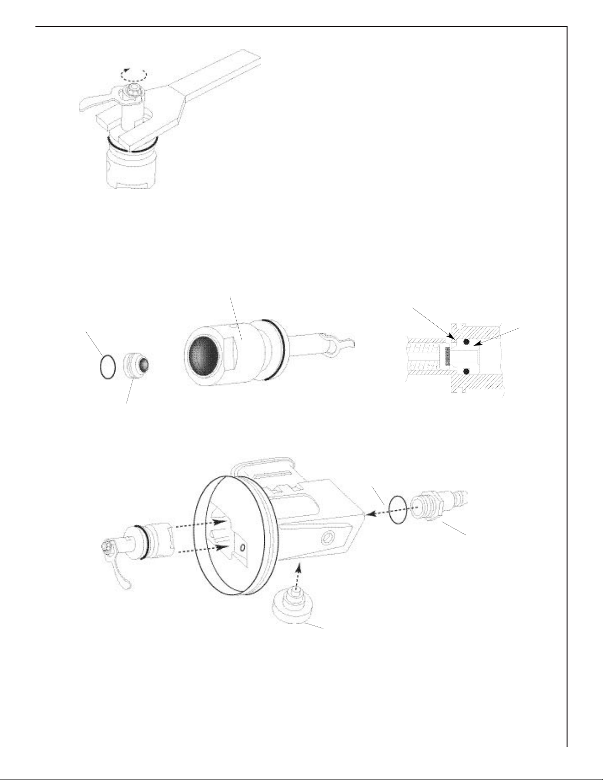
Using the special wrench APS010 to prevent
the valve from turning, unscrew the nyloc nut
(take note of how far the nut is screwed on
the valve to assist reassembly) and remove the
lever and nylon anti-friction washers.
The valve stem is spring loaded, so cover the
QD opening and leave the ASP010 tool insert-
ed to keep these parts from escaping.
Carefully remove the APS010 tool, catching
the parts as they “spring” out the open end.
The rubber valve seating (Item #9) can now
be removed and replaced.

The valve body (Item 2) and the casing (Item 17)
have corresponding location flats to prevent possible
movement of the valve body in service. The ridge in
the casing is not strong enough to prevent turning of
the valve body when tightening the QD nipple.
A special service tool APTP28 must be used oth-
erwise damage to the casing is possible.
Using the service tool APTP28, put into position to
prevent the valve body turning, unscrew the QD nip-
ple about 3/16". When the nipple is loose, remove
the service tool and use the partially unscrewed nip-
ple to help push the valve body out of the casing,
then proceed to unscrew and remove QD nipple.
APTP28
O-Ring #10
Item #8
Val v e B o d y
Section
Item #8
☛

Always fit a new valve core (Item 31) if there
is any doubt about the integrity of this item.
Press the valve core firmly into the body while
turning it to ensure that the thread engages
properly, tighten securely into position.
Do not over-tighten as this may cause dam-
age to the core mechanism or seal.
The shoulder of the core should be level with
or just below the diameter of the valve body.
2.4 RE-ASSEMBLING THE POWER INFLATOR
NOTE: Do not separate the regulator case
(Item 17) and oral inflator body (Item 11)
except to replace the ‘O’ ring (Item 13).
Remove the posidrive screw behind the lever to
release the oral inflator body which can now be
slid off its dove tail.
Removing the posidrive screw in the button
will release all the remaining components. Use
the fork end of the special OCTO+ wrench,
APS010, to prevent the valve turning.
Check the condition of the rubber valve seating
and seat.
Assembly is in the reverse order. Do not
over-tighten the posidrive screws.
2.5 REMOVE AND DISMANTLE THE ORAL INFLATOR/DEFLATOR
Replace the flexible rubber button, support and
lock ring (Items 28, 29 and 30)
Seal
Fig. 5
0.03” MAX
Item# 28
Item# 29
Item# 30
Item# 31
Seal
Item# 27
Item# 26
Item# 11
Item# 16
Item# 33
Item# 32
Item# 35
Item# 34
Item# 13
O-Ring ☛
☛
Remember approximately how far to screw on the
nyloc nut to the stem.
Using the special OCTO+ wrench to prevent the
valve turning, replace the nyloc nut to approximately
the same position prior to removal.
IMPORTANT
Ensure that the plastic friction insert in the nut is
in good condition, to prevent the nut unscrewing
during use. Renew the nut if any doubt.
Lightly lubricate the '0' ring (Item 14) and carefully
replace the valve seat (Item 6) in the body ensuring
that it is pushed fully up to the shoulder (See fig. 3).
The valve assembly can now be replaced in the case
and aligned as shown to ensure "flats" on the body and
in the case line up.
Fig. 3
Item #14 O-Ring
Item #6
Item #2
☛
☛
Place tool APTP28 in proper position, then
place QD nipple into place with proper torque.
Item #8
Item #10 O-Ring
APTP28
Hard up to shoulder Val v e s e a t
Item #6

Inspect the diaphragm (Item 21) and
exhaust valve (Item 20) for perforations or
cracks, especially along the edge and on the
"spider" where the exhaust valve attaches.
Replace if any are found.
Fit diaphragm (with exhaust valve installed)
on case, being sure the edge of the
diaphragm is in place on the case.
Place end cover over diaphragm and secure
with locking ring (Item 18)
SECTION 4 - QUICK DISCONNECT FITTING
The regulator may be fitted with one of several
similar types of QD coupling.
In all cases it is essential that the sleeve must
slide up to the shoulder of circlip when fitted
on the nipple. If the sleeve does not slide com-
pletely up to the shoulder when pushed into
place, it is possible for accidental disconnection
to occur.
Position of Sleeve when fitted
Item #17
Item #19
Item #21
Item #20
Item #22
Item #18 ☛
☛
Table of contents
Other Zeagle Diving Instrument manuals

Zeagle
Zeagle N2iTion3 User manual

Zeagle
Zeagle Buoyancy Compensator User manual

Zeagle
Zeagle Tiger performance T-310SSL User manual

Zeagle
Zeagle Flathead-7 User manual

Zeagle
Zeagle N2ition User manual

Zeagle
Zeagle 1BCD User manual

Zeagle
Zeagle Envoy Octo 320-3110 User manual

Zeagle
Zeagle Octo-Z 320-7200YL User manual

Zeagle
Zeagle ReZort 310-5210 User manual

Zeagle
Zeagle Flathead VI User manual


