Yuwa HD Series User manual
www.yuwatv.com
HD
SERIES
USER
MANUAL
24HD 32HD
A-4/14, Sector-80, Phase-II
Noida-201305
www.yuwatv.com
1800-1027-401
@yuwaledtv
@yuwaledtv
LED TV
CONTENTS
INTRODUCTION
WARNING AND SAFETY PRECAUTIONS
TV BRACKET ASSEMBLY
ANTENNA AND EXTERNAL CONNECTION EQUIPMENT
NAME AND FUNCTIONS OF CONTROL ON SET
BATTERY INSTALLATION
2. WARNINGS AND SAFETY PRECAUTIONS
Thank you for choosing our product. You can use it as a color television or as a PC
monitor. To be able to make use of all application options, we recommend that you
should read this operation manual carefully and keep it somewhere you have quick
access to, if required.
Do not touch any parts in the set and do not make changes to any settings not described
in this operating manual.
The LED Screen is a high-tech product consisting of more than 9,00,000 control elements.
Any Non-active red, blue or green spots that might appear on the screen occasionally,
have no effect on the performance of the screen or television.
To prevent damage to the TV which may result in a fire or electrical shock hazard, do not
expose the TV set to rain or excessive moisture.
Do not rub or strike the Active matrix LED with any thing hard as this may scratch, mark
or damage the active matrix LED permanently.
For safety, do not place vessels or any container which contain fluid including water, on
or near the TV.
Do not insert any objects in the ventilation slots.
Do not remove the back cover of the set as this can expose you to very high voltage and
other hazards. If the set does not operate properly, unplug it and call service person.
Warning:
Service:
Connect the antenna cable to the socket marked ANT IN on the back cover. For
best reception an outdoor antenna should be used.
Antenna:
Position the set so that no bright light or sunlight falls directly on the screen.Reflections
on the screen affects the picture quality.
Soft and indirect lighting is recommended for comfortable viewing.
Care should be taken not to expose the set to any unnecessary vibration, moisture, dust
or heat.
Adequate ventilation is essential to prevent set failure.Ensure that the set is placed in a
position to allow a free flow of air. Do not cover ventilation opening on the back cover.
Do not place the set in an enclosure or very close to walls.
Avoid excessively warm locations to prevent possible damages to the set.
Place the television on a solid and flat surface.
Location:
1. INTRODUCTION
21
2
2-3
3-4
5
6
NAME AND FUNCTIONS OF CONTROL ON REMOTE 7
7
PICTURE MENU
SOUND MENU
OPTION MENU
MEDIA
8
8
8
8
USB TO USB Copy 9
TIMER MENU 9
No warranty claims are accepted for damage caused due to incorrect handling.
This LED TV Set is designed to receive display video and audio signals and for use as
a PC monitor. Any other use is prohibited.
Despite the high quality of the television, random disturbances or interference may
cause occasional malfunctioning. In this case the correct function of the apparatus can
be restored by switching off the TV through the main On/Off button or removing the
main plug, then switch ON as soon as the LED light disappears.
Cautions.
Note:
For safety, remove the AC plug from the wall outlet before cleaning the set.
Clean the dust on set by wiping the screen and the cabinet with a soft, clean cloth. If the
screen requires additional cleaning, use a clean damp cloth. Do not use liquid cleaners
or aerosol cleaners or liquid containing benzol, petroleum or chemicals.
Cleaning:
Do not allow anything to rest upon or roll over the power cord, and do not place the set
where the power cord is subject to damage.
Remove the AC plug from the wall outlet when the TV set is not used for a prolonged
period of time.
In the event of thunder storms or power cuts please remove the main power plug and
aerial plug.
Unplug the set in case of abnormal operation e.g. smoke, odd sound or smells.
Use the main power cord provided for connecting the TV.
Power:
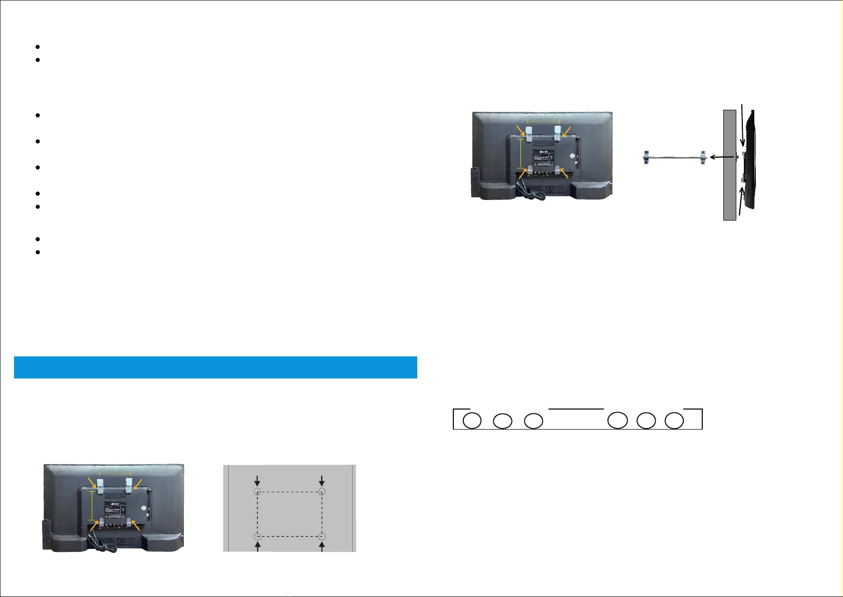
3. TV WALL MOUNT ASSEMBLY
Fixing the LED TV on a wall
1. First, place the LED TV on a table smoothly and place a soft cloth on the table to avoid
scratching the screen.
2. Use a screw driver to take off the screws which are fixed on the bottom stand (Refer to Fig. 1,
direction of the arrows) and take out the bottom stand (please keep the screws and bottom
stand carefully)
Fig1
43
3. Make one bracket which can be fixed on the wall according to the size of arrow direction of fig. 2 and fig. 3.
4. Drill four holes on the wall (the size is given only for reference) and fix the TV Wall Mount
bracket on the wall. (This is optional,you may place the tv using a table stand only)
5. Use a screwdriver to lock the screws in the wall mount bracket on the back of the TV,
then hang the TV on the wall.
NOTE:
The bracket fixed on the wall is an optional part.
When you fix wall mount on the TV, there should be no other articles on, around and front
of the TV and please keep a distance from any product hampering articles.
The fixing picture is only for reference.
Attach the mounting bracket from the VESA compatible wall mounting kit.
1.
2.
3.
4.
(NOTE : The stand screws will be in bottom side.)
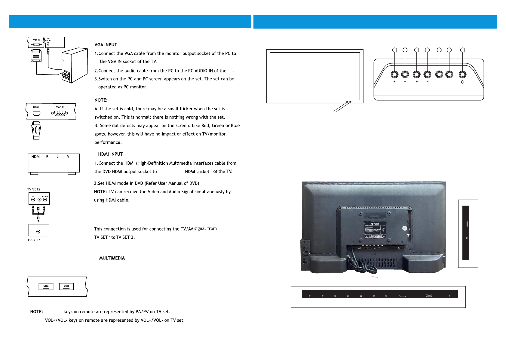
AV INPUT1 / INPUT2
1.Connect the composite outputs (Video, L & R) of VCR/DVD Player to AV INPUT 1 / INPUT2.
2.1 Press the Input button on the remote to select AV1/AV2.
AV Input-1
VL R
AV Input-2
VLR
NOTE : Selecting a Source
Remote Control :
Press Input button on the remote control to display' Input source OSD'. Then choose any source by
pressing Up/Down button and Press Enter to select it.
TV Control Panel :
Press Source button and choose any source by pressing Prog+ / - button and Press source
button again to select it.
Fig1a wall
100 mm
100 mm
100 mm
100 mm
support clamp
Fig3
wall
Wallmount
Hanging Clamp
ROD
100 mm
200 mm
100 mm
200 mm
6
UP/Down
Connect/Insert standard USB pendrive. Select on source OSD by
pressing Input key, Press Left/ Right key on remote to choose
photo / Music / Movie /text. Similarly TV panel keys Prog +/-
can be used as Up/Down and Vol+/- for selecting media content
and Press Prog+ to select.
4. ANTENNA AND EXTERNAL CONNECTION EQUIPMENT
TV
IN
AV output
AV OUTPUT
2
either of the 2
s
5
1.
2.
3.
4.
5.
6.
7.
8.
9.
10.
IR SENSOR
LED INDICATOR
STANDBY
CH+
CH-
VOL+
VOL-
MENU
SOURCE (TV/AV)
AC POWER CORD.
11.
12.
13.
14.
15.
16.
17.
18.
19.
20.
21.
22.
RF
USB 1, USB 2
PC AUDIO IN
VGA IN
HDMI
AUDIO L
AUDIO R
AV INPUT 2
AUDIO L
AUDIO R
AV INPUT 1
EARPHONE
B) CONNECTING YOUR UNIT:-
9 7 6 5 4 3
5. NAME AND FUNCTION OF CONTROLS ON SET
A) TV Control Panel Buttons
8
SOURCEVOL MENU
2
1
Note:
Above sketches are just representation. Actual TV set may look differ than these sketches.
HDMI
AUDIO
R
Av2 L VGA In PC AUDIO
IN
EARPHONE
22 21 20 19 18 17 16 15 14 13
12 11
USB 1
USB 2
RF
IN
LAUDIO
R
AVI
IN
SET TOP BOX
Ch
10
8. PICTURE MENU
7
6. BATTERY INSTALLATION
1. Remove the battery compartment door.
2. Insert two pieces of 1.5V size UM-4 "AAA" batteries or equivalent
with the correct polarity as indicated by (+) and (-) symbols.
3. Close battery compartment door.
NOTE: Replace batteries when they are exhausted or if the remote
control is not to be used for a long time.
BATTERY PRECAUTIONS:
Incorrect use of batteries can cause electrolyte leakage which will
corrode the remote control or cause the batteries to burst.
Replace both batteries at same time.
Don't Mix batteries type (alkaline with carbon ,zinc etc.)
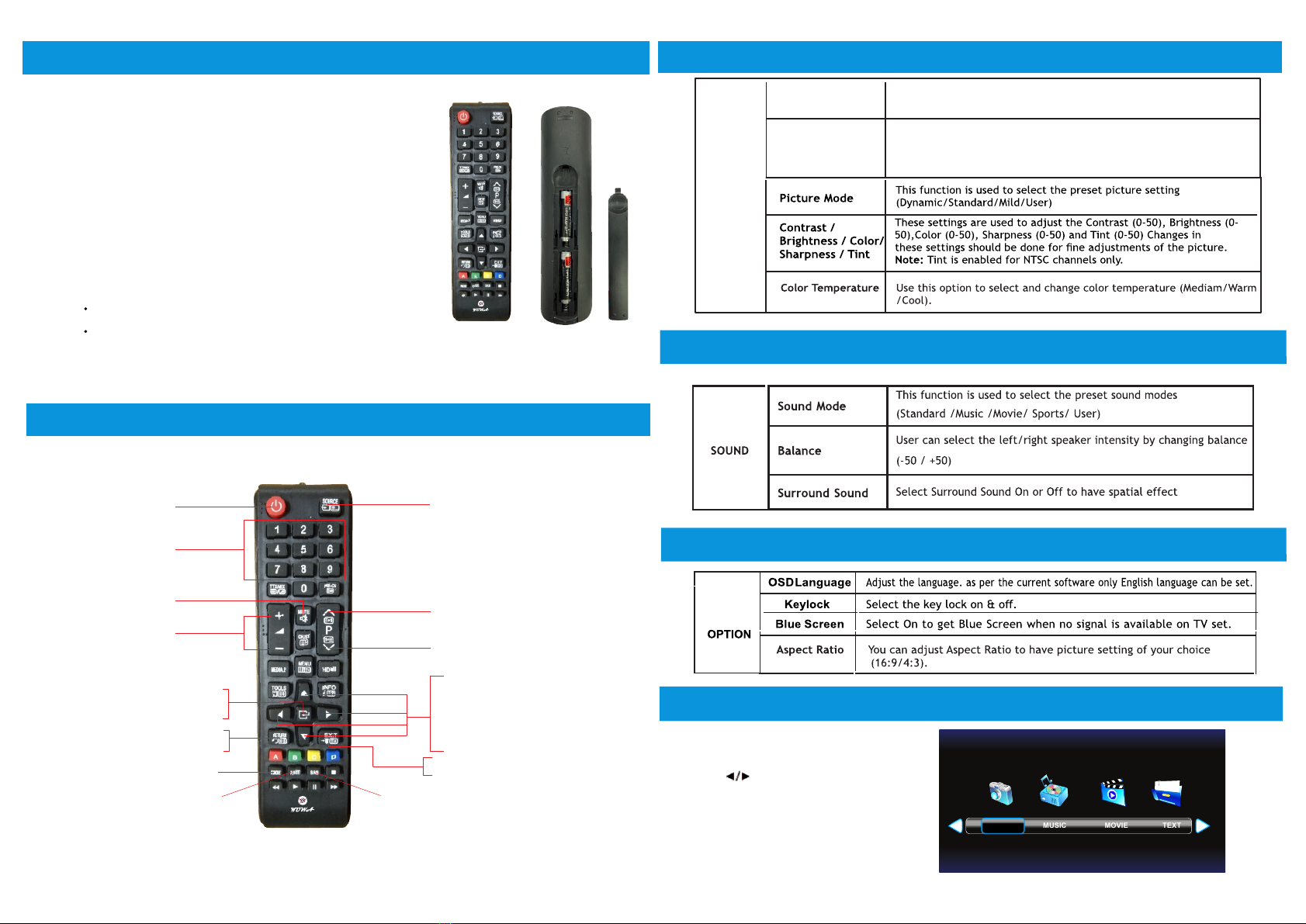
NAMES AND FUNCTION OF CONTROLS ON REMOTE
7.
Navigates Vertically up through the Menu/Sub Menus
To enter character/numbers in program name parameter
To navigate channel down through valid channels
Navigates horizontally right/left through the Menu/sub Menus.
To enter in Menu/Sub Menus and to adjust Vol +/-
To navigate the letter in program name parameter
To select the time
Increase/decrease the value of selected items and set the parameter On/Off
To enter in sub menu.
Enter to edit program name parameter
Press to exit the OSD menu
Figures 0-9 are used to
directly input channel number
To select menu OSD window and return to upper menu
Input source selection
Turns sound OFF or ON
Select to increase or
decrease volume
To select menu OSD
window and return to upper menu
To select the picture mode
To select the sound mode
To select the aspect ratio of screen
Picture Mode
Contrast /
Brightness / Color/
Sharpness / Tint
This function is used to select the preset picture setting
(Dynamic/Standard/Mild/User)
These settings are used to adjust the Contrast (0-100), Brightness (0-
100),Color (0-100), Sharpness (0-100) and Tint (0-100) Changes in
these settings should be done for fine adjustments of the picture.
Note: Tint is enabled for NTSC channels only.
PICTURE
11.
MEDIA
Press
"NO DEVICE" icon means TV has not
detected USB memory.
To select Photo/Music/Movie/Text icon
and ENTER to enter the USB memory.
Photo
8
Turns TV into STANDBY ON/OFF
9. SOUND MENU
10. OPTION MENU
8
MUSIC MOVIE TEXTPHOTO
109
Aspect Ratio You can adjust Aspect Ratio to have picture setting of your choice
(16:9/Panorama/Auto/4:3/14:9/Zoom/Cinema Zoom).
12. TIMER MENU
TIME
OSD Duration
Sleep
Timer
Select
the
time
in
minutes
(10min
to
90min)
in
which
you want
the
TV
to
shut
off
Auto
Sleep
Select the Auto sleep 3H to 5H
Adjust the appearance duration of TV display for 5 sec to 30 sec.
This manual suits for next models
2
Table of contents