York YMC2 User manual

JOHNSON CONTROLS 1
Startup Checklist
YMC2- Mod A
Supersedes 160.78-CL2 (421) Form 160.78-CL2 (1121)
Startup Checklist
The following work must be completed in accordance with the operation manual:
Customer: ______________________________________
Address: _______________________________________
Phone: _________________________________________
JCI tel no: _______________________ JCI order no: ______________________ JCI contract no: ___________________
Job name: ______________________________________
Location: _______________________________________
Customer order no: _______________________________
Chiller model no: _______________________________
The work (as checked below) is in process and will be completed by: _____________ / ____________ / ___________
Unit serial no: __________________________________
Month Day Year
A. General
Review the Installation Checklist, Form 160.78-CL1, to
validate the attributes have been completed. Attach a
completed copy for records.
1. Water connection inlet and outlet are at proper
locations, have hangers nearby that support their
weight and show no visible strain on chiller nozzles
2. Relief piping is complete and puts no strain on the
relief valves ..............................................................
3. Verify the chiller is charged with refrigerant
Pressures match R-134a saturation for ambient
temperature..............................................................
4. Verify the evaporator pressure transducer isolation
valve is open ............................................................
5. Verify the condenser pressure transducer isolation
valve is open ............................................................
6. Verify the discharge pressure transducer (stall
transducer) isolation valve is open...........................
7. Verify the compressor discharge isolation valve is
open .........................................................................
8. Verify that the liquid line isolation valve is open.......
9. Verify the hot gas bypass line isolation valve, if hot
gas is present, is open ..............................................
10. Verify the motor stator liquid cooling angle valve
just above the shells, below the motor is open .........
11. Verify the motor stator liquid cooling strainer service
capped ball valve above the motor is open...............
12. Verify the drive shipping antifreeze solution is
drained and fill with inhibited water that shipped
with the chiller, as outlined in the 160.00-M12
manual ......................................................................
13. Verify that the motor electrical connections are
tightened per the label on the back wall of the
drive.......................... ................................................
14. Check the chiller for refrigerant leaks at joints ..........
15. Ensure jumper installed on OptiView™ TB6 terminal
24 to 25 .....................................................................
16. If the unit is equipped with SC-EQ, set up in
accordance with 450.50-N1 Section 2 .....................

JOHNSON CONTROLS
2
Form 160.78-CL2
Issue date: 11/01/2021
17. For chilled water pumps, check the following:
a. Power is available................................................
b. Wiring is complete................................................
c. Check rotation......................................................
18. For condenser water pumps, check the following:
a. Power is available................................................
b. Wiring is complete................................................
c. Check rotation......................................................
19. For the cooling tower fan, check the following:
a. Power is available................................................
b. Wiring is complete................................................
c. Check rotation......................................................
Note: Do not check the compressor motor
B. Electrical wiring
1. Ensure that the incoming power wiring is not alu-
minum. Copper wire must be used...........................
2. All variable speed drive wiring connections must
be made in accordance with 160.78-PW1................
3. If the power source is transferrable from utility to
generator, and generator to utility, then ensure that
there is a 10 second delay between the transfers
of power sources......................................................
4. If power factor correction capacitors are applied
between the power source and the drive, then
they must be removed or turned off..........................
5. Variable Speed Drive:
a. Main power supply is available............................
b. Wiring completed from the main power supply
to the drive, but not connected.............................
Note: Do not cut power wire to length or connect power
wire to the drive without JCI supervision.
c. Verify that the conduit plate was removed when
the conduit holes were made...............................
d. Ensure that no metal shavings are present
on top of the circuit breaker, other electrical
components, or on the oor of the drive enclo-
sure......................................................................
e. Measure and cut power wire to length outside
of the drive enclosure. Use a tool designed to
cut large diameter power wire..............................
f. Ensure that the conduit connections are made
at the top of the drive at the conduit plate. No
other enclosure penetrations are allowed............
Note: Failure to use the conduit plate for the conduit
connection will require drive replacement at no cost to
JCI.
g. Power feed terminations to the drive are tight-
ened to the torque value listed on the circuit
breaker.................................................................
h. Verify that the circuit breaker settings match the
settings shown in the OptiSpeed™ drive service
manual. Refer to 160.78-M3................................
6. External control wiring is completed according to
the wiring diagram shipped with the unit. Refer to
160.78-PW2.............................................................
7. Meghometer is available for checking the motor
windings...................................................................
Note: Megger testing of the motor winding is not necessary
unless start-up indicates a motor winding shortage.

JOHNSON CONTROLS 3
Form 160.78-CL2
Issue date: 11/01/2021
C. Control panel
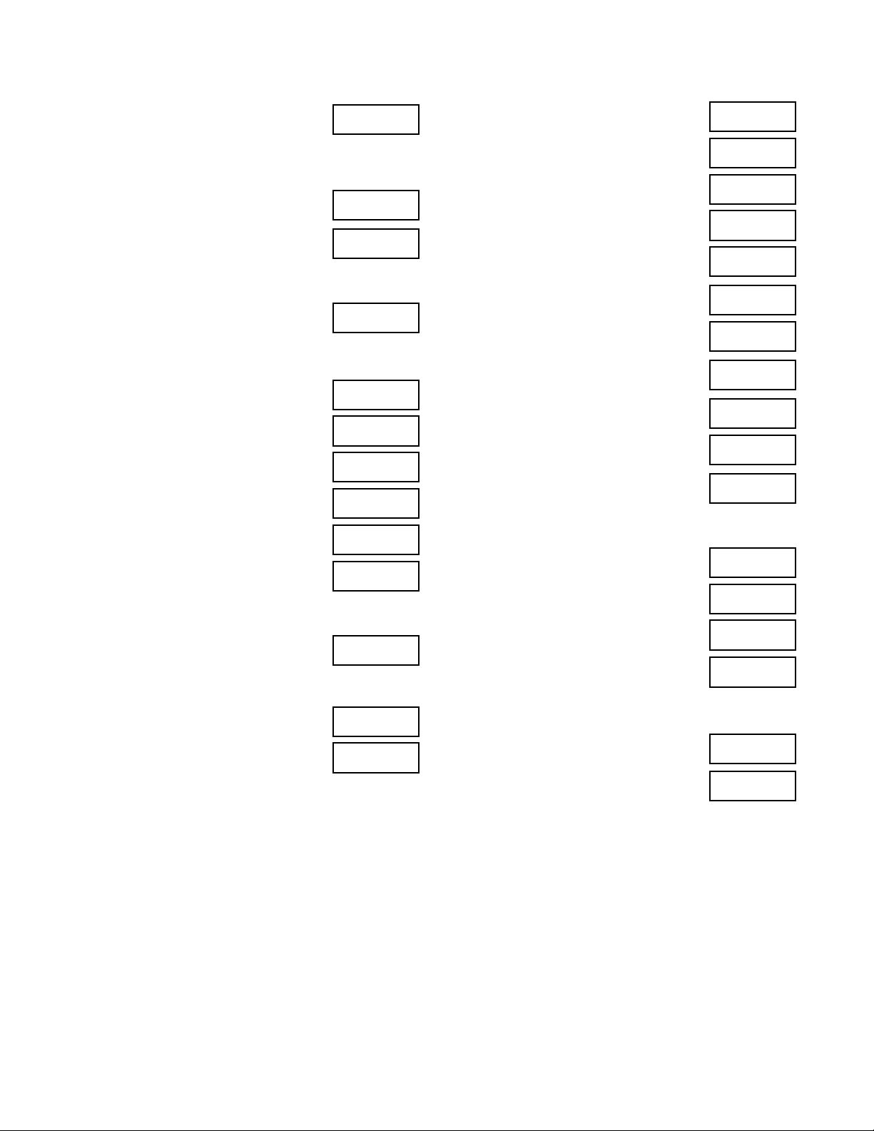
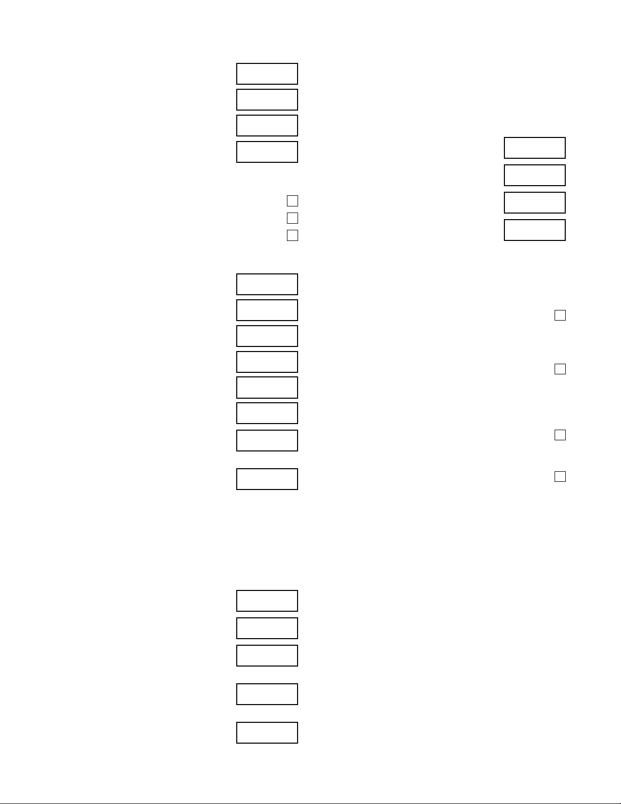
Log on at SERVICE level access to ensure access to the
necessary setpoints. The setpoints are grouped by the
screen in which they appear. Enter the as-left value in the
corresponding box for each setpoint.
Some are ADMIN-controlled chiller configuration and fac-
tory defaults that must not be changed. Those that cannot
be changed in SERVICE level access are identified with
(ADMIN) after the setpoint name and are intended only
to be validated and logged at SERVICE level. Those with
recommended settings for correct operation are designat-
ed with the setting in parenthesis after the setpoint. Oth-
ers do require specific setup for the site conditions and
consideration of the application. Those most likely requir-
ing site-specific setup are marked with italic text. Ensure
that each setting is logical for the chiller configuration and
application. Refer to forms 160.78-O2 and 160.78-M2
for procedures to perform calibrations or explanation of
setpoints.
Start by navigating to the Capacity Control - Setpoints
Screen and accept the default capacity control and level
control setpoints with the DEFAULT SETPOINTS button
on the bottom bar. Return to Home and navigate to each
of the following screens.
1. Setpoints:
Remote Analog Input Range ....................
2. Setpoints: Setup
Clock ........................................................
Enter Clock Time and Date ......................
Liquid Type
(Program Jumper dependent) ..................
Refrigerant Selection (fixed).....................
Line Voltage..............................................
Line Frequency.........................................
Chilled Liquid Pump Operation.................
Head Pressure Control.............................
Hot Gas Bypass .......................................
Flow Switch ..............................................
Power Failure Restart...............................
3. Setpoints: Setup: Schedule
Enable or Disable Scheduled Operation ..
Set up Site Schedule if required and
Enabled ....................................................
4. Setpoints: Setup: User
Data Display Mode...................................
System Language ....................................
Date Format .............................................
5. Setpoints: Setup: Comms
Baud.........................................................
Data Bits...................................................
Parity ........................................................
Stop Bits...................................................
COM 2 Setup............................................
Baud (ADMIN, 38400 required)................
Data Bits (ADMIN, 8 required)..................
Parity (ADMIN, None required) ................
Stop Bits (ADMIN, 2 required)..................
Chiller ID...................................................
6. Setpoints: Setup: Printer
Automatic Printer Logging........................
Log Start Time..........................................
Output Interval..........................................
Printer Type ..............................................
JOHNSON CONTROLS
4
Form 160.78-CL2
Issue date: 11/01/2021
7. Setpoints: Setup: Sales Order
Enter Commissioning Date
(record here).............................................
Compressor Model must be entered and must
be of the format M1B-xxxFAy, where (xxx) is
197 or 205 and (y) is either the ending A
or ending B in the compressor model
on the compressor nameplate..................
Ensure Data is entered and obtain a
print (Done) ..............................................
8. Setpoints: Setup: Operations
Control Source .........................................
9. Evaporator
Leaving Chilled Local Setpoint.................
Remote Range .........................................
Shutdown Offset.......................................
Restart Offset ...........................................
Refrigerant................................................
Smart Freeze............................................
10. Condenser
High Pressure Warning Threshold..........
11. Condenser: Refrigerant Level Control
Level Control Valve Mode (Auto) ............
Refr Level Setpoint (running)..................
12. Condenser: Refrigerant Level Control:
Setpoints
Startup Position ......................................
Startup Delay (ADMIN)...........................
Ramp Time (ADMIN) ..............................
Zone Transition Delta (ADMIN)...............
Zone Transition Time (ADMIN) ...............
Liquid Level: Zone 1 Proportional
(ADMIN)..................................................
Liquid Level: Zone 1 Integral (ADMIN) ...
Liquid Level: Zone 1 Derivative
(ADMIN)..................................................
Liquid Level: Zone 2 Proportional
(ADMIN)..................................................
Liquid Level: Zone 2 Integral (ADMIN) ...
Liquid Level: Zone 2 Derivative
(ADMIN)..................................................
13. Compressor: Surge Protection
Shutdown................................................
Count Window ........................................
Count Limit..............................................
Surge Sensitivity.....................................
14. Compressor: VGD
Diffuser Gap Control Mode (Auto) ..........
VGD Calibrate (Done).............................

JOHNSON CONTROLS 5
Form 160.78-CL2
Issue date: 11/01/2021
15. Compressor: VGD: Setpoints
Surge React Time...................................
Surge Wait Time .....................................
Probe Wait Time .....................................
Open Pulse.............................................
High Limit................................................
Low Limit.................................................
PRV VGD Inhibit.....................................
PRV Offset..............................................
16. Capacity Control Setpoints
LCHLT Setpoint Ramp Rate ...................
LCHLT Setpoint Start Offset ...................
*PRV Start Position.................................
*PRV Shutdown Position ........................
†VGD Start Position................................
†VGD Shutdown Position .......................
HGBP Start Position ...............................
Drive Start Frequency.............................
Drive Soft Shutdown Ramp Rate
(ADMIN)..................................................
Temperature Control Kp (ADMIN)...........
Temperature Control Ti (ADMIN) ............
Temperature Control Td (ADMIN)...........
Temperature Control Max Loading Delta
(ADMIN) .................................................
Temperature Control Max Unloading
Delta (ADMIN) ........................................
Drive Output Gain (ADMIN)....................
*PRV Output Gain (ADMIN)....................
†VGD Output Gain (ADMIN)...................
HGBP Output Gain (ADMIN) ..................
17. Capacity Control Setpoints:
Anti-Surge Tuning
*Minimum PRV Position..........................
Min Frequency Multiplier.........................
Min Frequency Offset .............................
Min Freq Rate - HGBP Closed (ADMIN)
Min Freq Rate - HGBP Open (ADMIN)...
Min Frequency Admin Multiplier
(ADMIN)..................................................
Transient Time Delay..............................
Transient Deadband ...............................
Transient Max Change ...........................
Min Frequency Mid Position ...................
Min Frequency Coefficient a1.................
Min Frequency Coefficient a2.................
Min Frequency Coefficient a3.................
Min Frequency Coefficient b1.................
Min Frequency Coefficient b2.................
Min Frequency Coefficient b3.................
*Max VGD Knee PRV (ADMIN)..............
*Max VGD Knee VGD (ADMIN)..............
*Max VGD Coefficient a (ADMIN)...........
*Max VGD Coefficient b (ADMIN)...........
Note:
* Compressor model ending in A only.
† Compressor model ending in B only.
JOHNSON CONTROLS
6
Form 160.78-CL2
Issue date: 11/01/2021
18. Variable Speed Drive
Input Job Full Load Amps .......................
Local Input Current Limit.........................
Pulldown Demand Limit..........................
Pulldown Demand Time..........................
19. Variable Speed Drive: Details
Test Mode (Disabled)..................................................
Manual DC Bus (Disabled) .........................................
Manual Cooling (Disabled) .........................................
20. Motor Details
Setpoint Offset ........................................
Min Housing Temp ..................................
Max Winding Temp .................................
Kp (ADMIN) ............................................
Ti (ADMIN)..............................................
Td (ADMIN).............................................
Motor Cooling Control State is set to
AUTO......................................................
Capture the chiller setpoints on a print
or text file from the Setpoints-Print
command................................................
21. Maintenance screen: Accessible for OptiView™
V08 or higher software
(Press: Home > Setpoints > Setup > Diagnostics >
Maintenance)
Press the Change Setpoints button to verify that each
of the five Service Warnings are enabled:
Quarterly Service Warning Enabled
(Admin access).......................................
Yearly Service Warning Enabled
(Admin access).......................................
3 Year Service Warning Enabled
(Admin access).......................................
Condenser High Small Temperature
Difference Warning Enabled
(Admin access).......................................
System Replace Filter Drier
Warning Enabled
(Service access) .....................................
To set the maintenance run time counter for commission-
ing to zero, press the Maintenance Acknowledge but-
ton. You can use the Maintenance Acknowledge but-
ton to scroll to each time-based counter and, using the
correct password, set the value to zero. Refer to Form
160.78-M2.
Days Since Last Quarterly Service
(Service access) .....................................
Days Since Last Yearly Service
(Service access) .....................................
Operating Hours Since Last Yearly
Service (Service access) ........................
Days Since Last 3 Year Service
(Service access) .....................................
D. Chiller system
1. Evaluate cooler and condenser water flow
indication compared to design information found
on the sales order. If shell pressure drop is used, it
must be within ±15% of the rating information .........
2. As the chiller is started, verify the refrigerant level
sensor tracks level from empty condenser to fully
flooded level sensor probe over the range of <10%
to nearly 100% (160.78-M2)....................................
3. Adjust condenser refrigerant liquid level setpoint
to a value that covers the subcooler top and
provides proper evaporator performance
(160.78-M1) with the chiller running steady.
Update value in Section B........................................
4. After the chiller is at full load at design Leaving
Chilled Liquid Temperature, capture the Operating
Data to print or save to text file ................................

Notes

5000 Renaissance Drive, New Freedom, Pennsylvania USA 17349 1-800-524-1330 Subject to change without notice. Printed in USA
Copyright © by Johnson Controls 2021 www.johnsoncontrols.com ALL RIGHTS RESERVED
Form 160.78-CL2 (1121)
Issue Date: November 1, 2021
Supersedes: 160.78-CL2 (421)
Other manuals for YMC2
4
Table of contents
Other York Chiller manuals

York
York YLUA Series User manual

York
York MAXE OPTIVIEW YK Operating instructions

York
York YCWL0056SE Owner's manual

York
York eco YCAS Series User manual

York
York YLAA Series Owner's manual

York
York YCAL0012EC Owner's manual

York
York HFC-134A User manual

York
York YCAL Series User manual

York
York W1LC420 User manual

York
York YT Millennium Manual

York
York UL R134A User manual

York
York YCAS0098EB Owner's manual

York
York YCAV0569 Owner's manual

York
York YCIV Series Owner's manual

York
York YK User manual

York
York YCAS Series Owner's manual

York
York YCAZ33BA3 User manual

York
York Millennium YCAS Series Owner's manual

York
York YK Series Installation manual

York
York YST Troubleshooting guide