YDLIDAR X4 User manual
X4
USER MANUAL
Shenzhen EAI Technology Co.,Ltd.
DOC #:01.13.000002
www.ydlidar.com

Copyright 2015-2021 EAI
CONTENTS
1YDLIDAR X4 LIDAR DEVELOPMENT KIT ....................................... 1
1.1 Development Kit ................................................................................. 1
2USAGE UNDER WINDOWS.............................................................. 2
2.1 Device Connection .............................................................................2
2.2 Driver Installation ...............................................................................3
2.3 Evaluation Software Usage................................................................5
2.3.1 Start Scanning...................................................................................................6
2.3.2 Data Storage......................................................................................................6
2.3.3 Display Mean and Standard Deviation............................................................6
2.3.4 Play and Record................................................................................................7
2.3.5 Debug.................................................................................................................8
2.3.6 Filter...................................................................................................................8
3LINUX ROS OPERATION.................................................................. 9
3.1 Device Connection .............................................................................9
3.2 Compile and Install YDlidar-SDK.......................................................9
3.3 ROS Driver Installation.......................................................................9
3.4 Run the ydlidar_ros_driver .............................................................. 10
3.5 RVIZ View Scan Results................................................................... 10
3.6 Modify Scan Angle............................................................................11
4CAUTION......................................................................................... 12
4.1 Ambient Temperature....................................................................... 12
4.2 Ambient Lighting .............................................................................. 12
4.3 Power Supply.................................................................................... 13
5REVISE ............................................................................................ 14
Copyright 2015-2021 EAI
1 / 14
1YDLIDAR X4 LIDAR DEVELOPMENT KIT
The development kit of YDLIDAR X4 lidar (hereinafter referred to as X4) is an
accessory tool provided for performance evaluation and early development of the X4.
Through the X4 development kit, and with the evaluation software, users can observe point
cloud data scanned by X4 on your environment or development on the SDK.
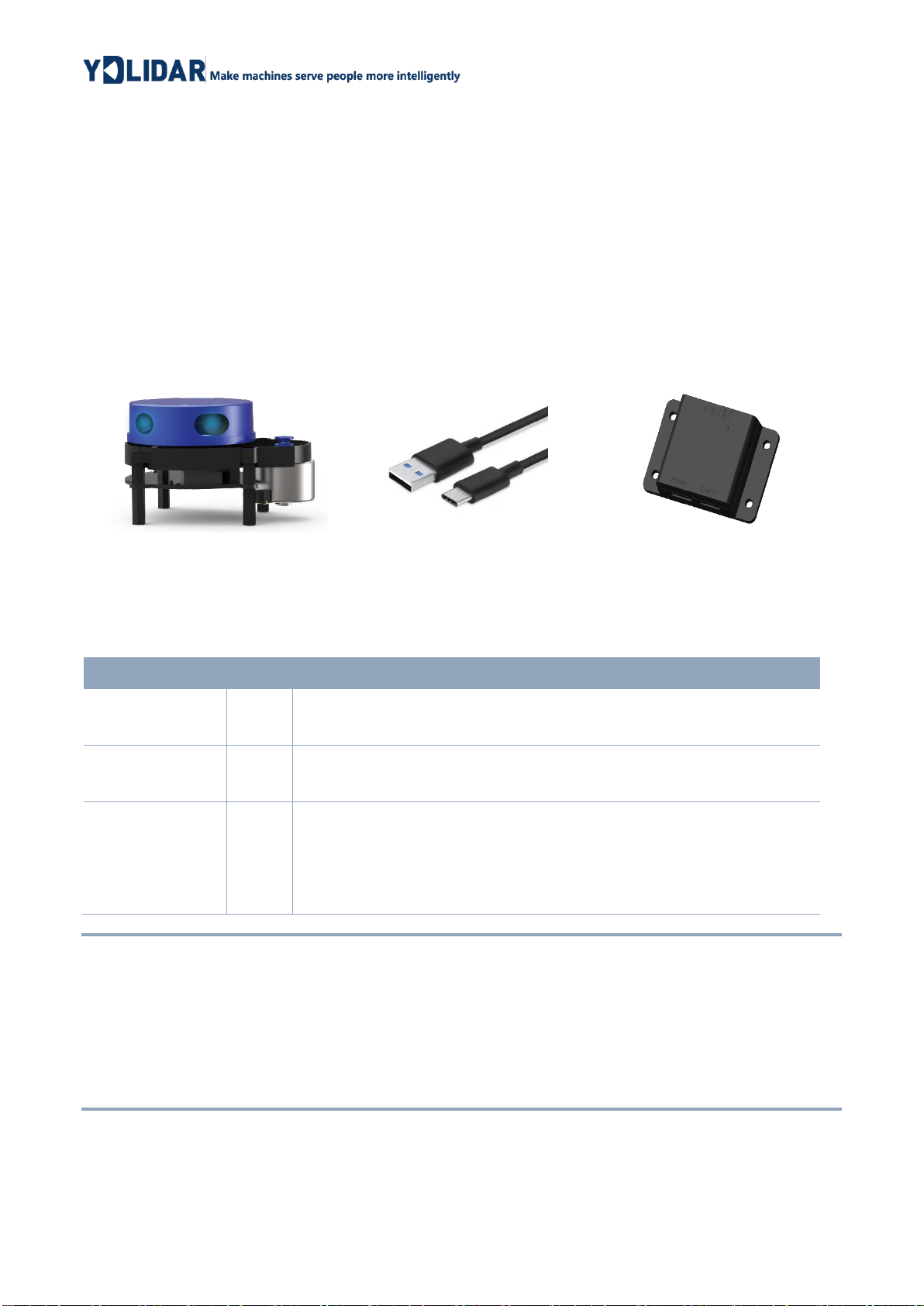
1.1 Development Kit
The X4 development kit has the following components:
FIG 1 YDLIDAR X4 DEVELOPMENT KIT
CHART 1 YDLIDAR TG SERIES LIDAR DEVELOPMENT KIT DESCRIPTION
Item
Qty.
Description
X4 lidar
1
Standard version of the X4 Lidar. The X4 has an integrated motor
drive for despin control and motor control.
USB Type-C
Cable
1
Use with USB adapter board to connect X4 and PC. USB cable is
both a power supply cable and a data cable.
USB Adapter
Board
1
Realize the function of USB to UART, which is convenient for the
fast interconnection between X4 and PC. Serial port DTR signal to
control X4 motor rotation and stop. In addition, a Micro USB
power interface (PWR) for auxiliary power supply is provided.
Note: USB Adapter board has two USB TYPE C interface:USB_DATA、USB_PWR.
USB_DATA: Data powered interface. In most cases, this interface can be used to meet power and
communication requirements.
USB_PWR: Auxiliary power supply interface. The USB interface of some development platforms
has weak current drive capability. At this time, auxiliary power supply can be used.
X4 Lidar
USB Type-C Cable
USB Adapter Board
Copyright 2015-2021 EAI
2 / 14
2USAGE UNDER WINDOWS
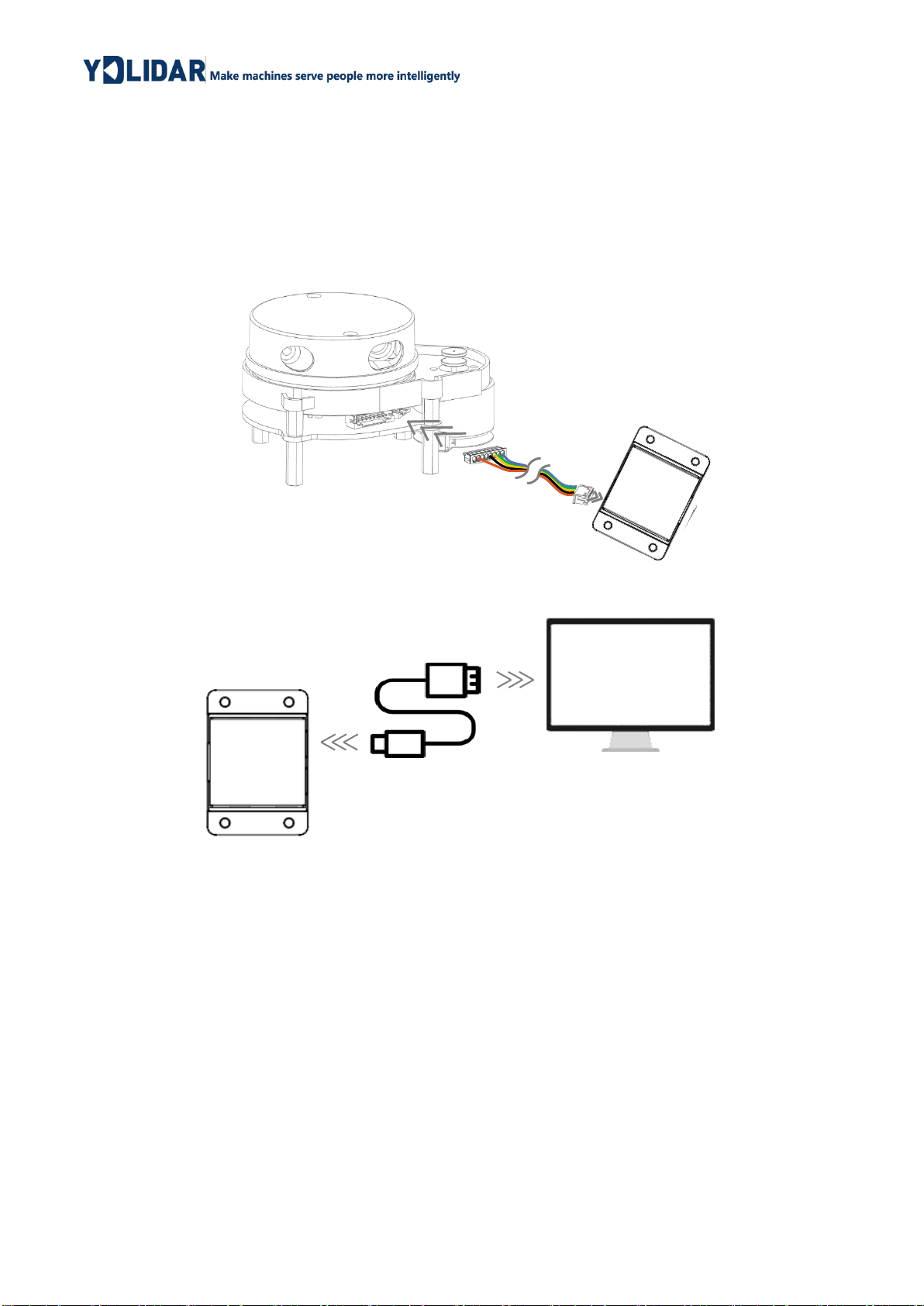
2.1 Device Connection
When evaluating and developing X4 under windows, you need to interconnect X4 and
PC. The specific process is as follows:
FIG 2 YDLIDAR X4 DEVICE CONNECTION STEP 1
FIG 3 YDLIDAR X4 DEVICE CONNECTION STEP 2
Connect the adapter board with X4 first, then connect the USB cable to the USB port of
the adapter board and the PC. Note that the Type-C interface of the USB cable is
connected to the USB_DATA of the USB adapter board, and the idle mode is used after X4
is powered on. The motor does not rotate.
The drive current of USB interface of some development platforms or PC is not
sufficient. X4 need to be connected to the auxiliary power supply of +5V, otherwise the lidar
will be abnormal.
Copyright 2015-2021 EAI
3 / 14
FIG 4 YDLIDAR X4 AUXILIARY POWER SUPPLY
2.2 Driver Installation
To evaluate and develop the X4 under Windows, you need to install the serial port
driver of the USB adapter board. The USB adapter board of this kit adopts CP2102 chip to
realize serial port (UART) to USB signal conversion. Its driver can be downloaded from our
official website or downloaded from the official website of Silicon Labs.
https://www.ydlidar.com/dowfile.html?id=97
http://cn.silabs.com/products/development-tools/software/usb-to-uart-bridge-vcp-drivers
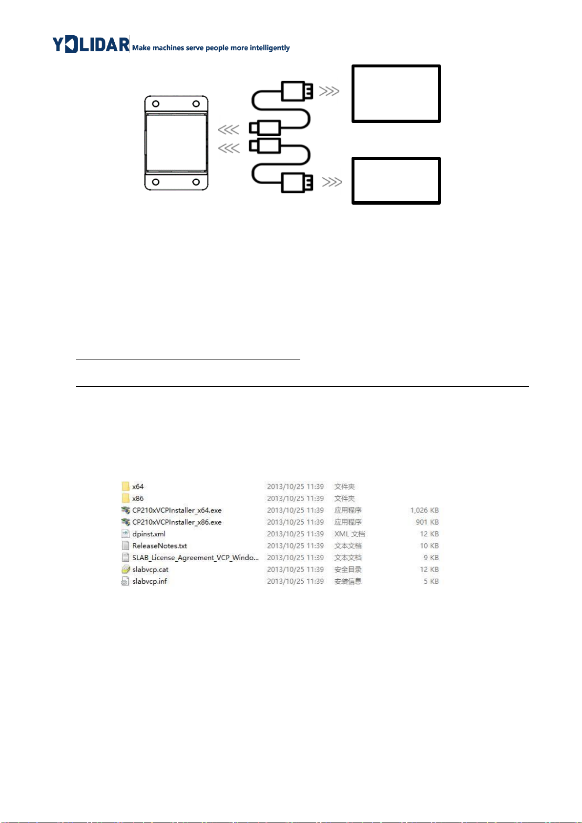
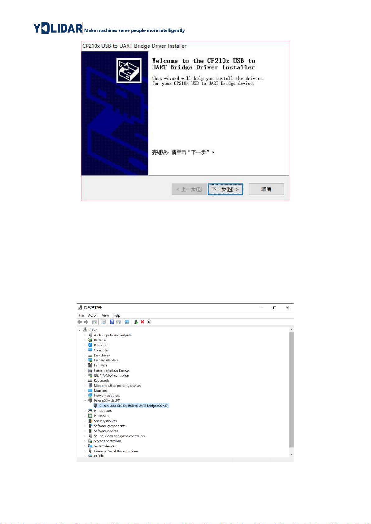
After decompressing the driver package, run the CP2102's Windows driver installation
file (exe file under CP210x_VCP_Windows). Please select the 32-bit version (x86) or 64-bit
version (x64) installation program according to the version of the windows operating
system.
FIG 5 YDLIDAR X4 DRIVER VERSION SELECTION
Double-click the exe file and follow the prompts to install it.
Development
Platform
5V Power
Supply
Copyright 2015-2021 EAI
4 / 14
FIG 6 YDLIDAR X4 DRIVER INSTALLING
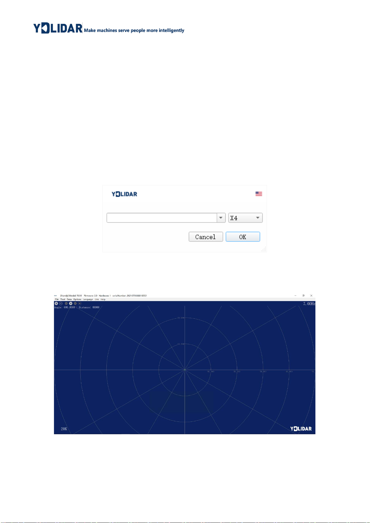
After the installation is complete, you can right-click on [My Computer] and select
[Properties]. On the open [System] screen, select [Device Manager] from the left menu to
access the [Device Manager].
Expand [Port] to see the serial port name corresponding to the identified USB adapter,
that is, the driver installation is successful. The following figure shows COM3. (Note that the
port must be checked in case of X4 and PC interconnection).
FIG 7 YDLIDAR X4 DRIVER INSTALLATION CHECK
Copyright 2015-2021 EAI
5 / 14
2.3 Evaluation Software Usage
YDLIDAR provides Point Cloud Viewer, a point cloud data visualization software
LidarViewer for X4 real-time scanning. Users can intuitively observe the X4 scanning effect
chart. GDL real- time point cloud data and real-time scanning frequency are provided on
YDLIDAR. At the same time, the version information of X4 can be read, and you can save
the scanned data offline to an external file for further analysis
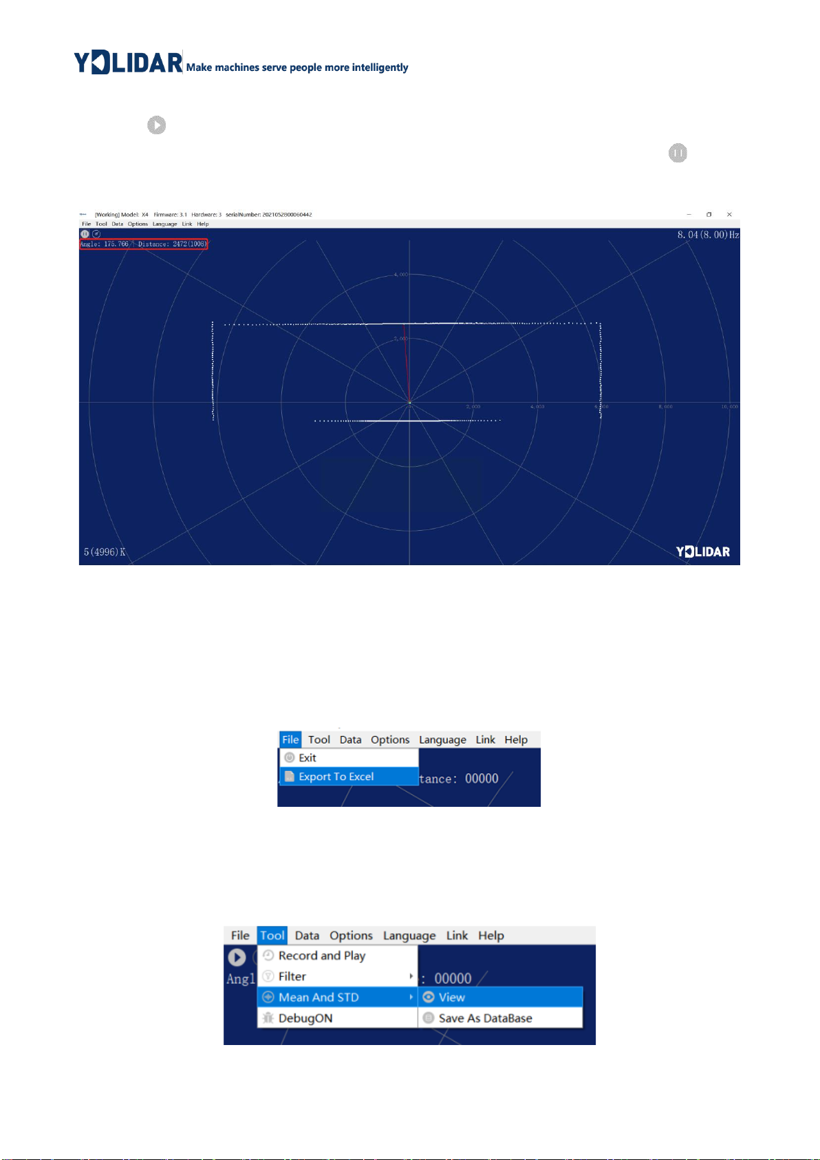
Before using the YDLIDAR software, make sure that the X4 USB adapter board serial
port driver is installed successfully, and interconnect the X4 with the USB port of the PC.
Run the evaluation software: LidarViewer.exe, select the corresponding serial port number
and model number. You could tick the square box to choose power off protection function.
Meanwhile, users could choose language and software type on the top right corner.
FIG 8 YDLIDAR X4 EVALUATION SOFTWARE
If the connection is correct, you will see the following screen:
FIG 9 POINTCLOUD VIEWER INTERFACE
Copyright 2015-2021 EAI
6 / 14
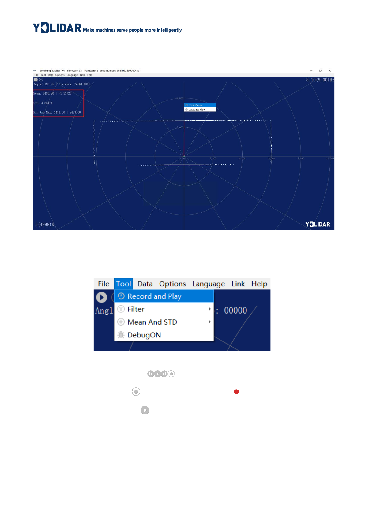
2.3.1 Start Scanning
Click to start scanning and display the environment point cloud, the upper left corner
displays the angle & distance information of the red line position (unit: mm). Click to stop
it. as shown below:
FIG 10 LIDAR SCANNING POINT CLOUD DISPLAY
2.3.2 Data Storage
During lidar scanning, click [File] in the main menu, select [Export to Excel], and save
point cloud data according to the prompts. Then the system will save the point cloud
information scanned in a circle in Excel format.
FIG 11 SAVE DATA
2.3.3 Display Mean and Standard Deviation
Click [Tools] in the main menu, then select [Mean And STD] - [View].
FIG 12 YDLIDAR G4 DISPLAY MEAN AND STANDARD DEVIATION
Copyright 2015-2021 EAI
7 / 14
Choose one according to your needs, move the mouse to the test position, right-click
the pop-up menu, and select [Lock Mouse Tracking].
FIG 13 LOCK MOUSE TRACKING
2.3.4 Play and Record
Click [Tools] in the main menu, then select [Record and Play].
FIG 14 RECORD AND PLAY
The main window is displayed as follows:
To record lidar data, click to start recording, and click to stop recording.
In non-scanning mode, click to start play.
The play process is as follows:
Copyright 2015-2021 EAI
8 / 14
FIG 15 PLAY PROCESS
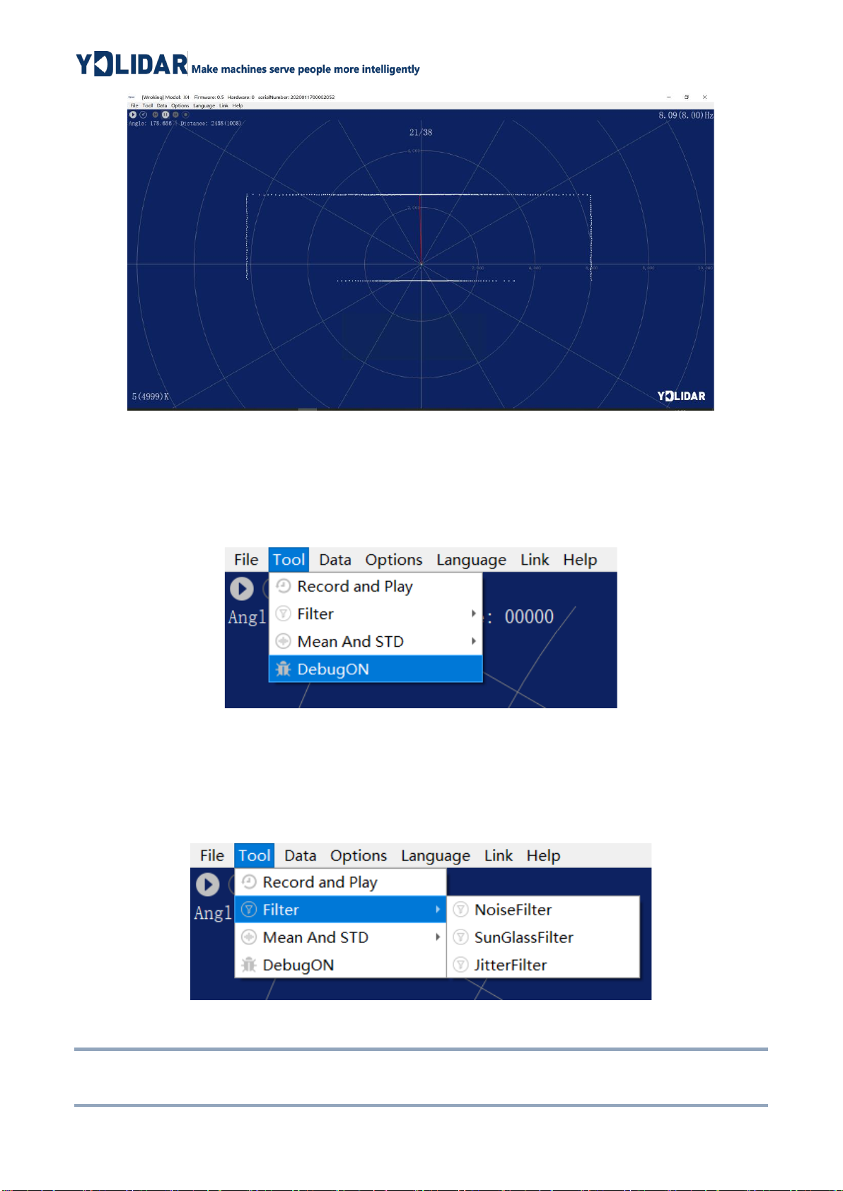
2.3.5 Debug
Click [Tools] in the main menu, and then select [DebugON] to output the raw lidar data
to the "viewer_log.txt" and "viewer_log_err.txt" files.
FIG 16 START DEBUGGING
2.3.6 Filter
Click [Tools] in the main menu, and then select [Filter] to add lidar data filtering
algorithm.
FIG 17 FILTER SETTING
Note: For more functions of LidarViewer, please click [Help], select [More Information], and learn more
about how to use it.
Other manuals for X4
3
Table of contents
Other YDLIDAR Microcontroller manuals

Popular Microcontroller manuals by other brands

AMS
AMS AS7261 Demo Kit user guide

Novatek
Novatek NT6861 manual

Espressif Systems
Espressif Systems ESP8266 SDK AT Instruction Set

Nuvoton
Nuvoton ISD61S00 ChipCorder Design guide

STMicrolectronics
STMicrolectronics ST7 Assembler Linker user manual

Texas Instruments
Texas Instruments Chipcon CC2420DK user manual


Texas Instruments
Texas Instruments TMS320F2837 D Series Workshop Guide and Lab Manual

CYPRES
CYPRES CY14NVSRAMKIT-001 user guide

Texas Instruments
Texas Instruments INA-DUAL-2AMP-EVM user guide

Espressif Systems
Espressif Systems ESP8266EX Programming guide

Abov
Abov AC33M8128L user manual

Laird
Laird BL654PA user guide