YASKAWA VIPA PBR Series User manual

PBR | 920-1CA50 | Manual
HB153 | PBR | 920-1CA50 | en | 19-09
VIPA Networking Solutions
PROFIBUS MultiRepeater A5
www.vipa.com/en/service-support/manuals

920-1CA50_000_PBMR-A5,4,GB - © 2019
VIPA GmbH
Ohmstr. 4
91074 Herzogenaurach
Telephone: +49 9132 744-0
Fax: +49 9132 744-1864
Email: [email protected]
Internet: www.vipa.com

Table of contents
1 General.................................................................................................................... 4
1.1 Copyright © VIPA GmbH ................................................................................. 4
1.2 About this manual............................................................................................. 5
1.3 Safety information............................................................................................. 5
2 Product Description............................................................................................... 7
2.1 General............................................................................................................. 7
2.2 Product features............................................................................................... 8
2.3 Application areas.............................................................................................. 9
2.4 Additional Benefits............................................................................................ 9
2.5 Channel Structure............................................................................................. 9
2.6 Grounding System.......................................................................................... 10
2.7 Cable lengths for PROFIBUS DP................................................................... 10
2.8 Cable types for PROFIBUS DP...................................................................... 11
2.9 Status display................................................................................................. 12
3 Installation Instructions....................................................................................... 13
3.1 Location.......................................................................................................... 13
3.2 Position........................................................................................................... 13
3.3 Mounting......................................................................................................... 13
3.4 Power Supply................................................................................................. 14
3.5 Backbone........................................................................................................ 14
3.6 Spur Segments............................................................................................... 16
3.7 Termination..................................................................................................... 16
3.8 Baudrate switch.............................................................................................. 17
4 Technical data ...................................................................................................... 18
5 Glossary................................................................................................................ 20
VIPA Networking Solutions Table of contents
HB153 | PBR | 920-1CA50 | en | 19-09 3

1 General
1.1 Copyright © VIPA GmbH
This document contains proprietary information of VIPA and is not to be disclosed or used
except in accordance with applicable agreements.
This material is protected by the copyright laws. It may not be reproduced, distributed, or
altered in any fashion by any entity (either internal or external to VIPA), except in accord-
ance with applicable agreements, contracts or licensing, without the express written con-
sent of VIPA and the business management owner of the material.
For permission to reproduce or distribute, please contact: VIPA, Gesellschaft für Visuali-
sierung und Prozessautomatisierung mbH Ohmstraße 4, D-91074 Herzogenaurach, Ger-
many
Tel.: +49 9132 744 -0
Fax.: +49 9132 744-1864
EMail: [email protected]
http://www.vipa.com
Every effort has been made to ensure that the information contained in
this document was complete and accurate at the time of publishing. Nev-
ertheless, the authors retain the right to modify the information.
This customer document describes all the hardware units and functions
known at the present time. Descriptions may be included for units which
are not present at the customer site. The exact scope of delivery is
described in the respective purchase contract.
Hereby, VIPA GmbH declares that the products and systems are in compliance with the
essential requirements and other relevant provisions. Conformity is indicated by the CE
marking affixed to the product.
For more information regarding CE marking and Declaration of Conformity (DoC), please
contact your local VIPA customer service organization.
VIPA, SLIO, System 100V, System 200V, System 300V, System 300S, System 400V,
System 500S and Commander Compact are registered trademarks of VIPA Gesellschaft
für Visualisierung und Prozessautomatisierung mbH.
SPEED7 is a registered trademark of profichip GmbH.
SIMATIC, STEP, SINEC, TIA Portal, S7-300, S7-400 and S7-1500 are registered trade-
marks of Siemens AG.
Microsoft and Windows are registered trademarks of Microsoft Inc., USA.
Portable Document Format (PDF) and Postscript are registered trademarks of Adobe
Systems, Inc.
All other trademarks, logos and service or product marks specified herein are owned by
their respective companies.
All Rights Reserved
EC Conformity Declaration
Conformity Information
Trademarks
VIPA Networking Solutions
General
Copyright © VIPA GmbH
HB153 | PBR | 920-1CA50 | en | 19-09 4

Contact your local VIPA Customer Service Organization representative if you wish to
report errors or questions regarding the contents of this document. If you are unable to
locate a customer service centre, contact VIPA as follows:
VIPA GmbH, Ohmstraße 4, 91074 Herzogenaurach, Germany
Telefax: +49 9132 744-1204
EMail: [email protected]
Contact your local VIPA Customer Service Organization representative if you encounter
problems with the product or have questions regarding the product. If you are unable to
locate a customer service centre, contact VIPA as follows:
VIPA GmbH, Ohmstraße 4, 91074 Herzogenaurach, Germany
Tel.: +49 9132 744-1150 (Hotline)
EMail: [email protected]
1.2 About this manual
This manual describes the PROFIBUS MultiRepeater 920-1CA50 from VIPA. It contains a
description of the construction, project implementation and usage.
Product Order number as of state:
HW
PBMR-A5 920-1CA50 01
The manual is targeted at users who have a background in automation technology.
1.3 Safety information
The system is constructed and produced for:
ncommunication and process control
ngeneral control and automation tasks
nindustrial applications
noperation within the environmental conditions specified in the technical data
ninstallation into a cubicle
DANGER!
This device is not certified for applications in
– in explosive environments (EX-zone)
The manual must be available to all personnel in the
nproject design department
ninstallation department
ncommissioning
noperation
Information product sup-
port
Technical support
Objective and contents
Target audience
Applications conforming
with specifications
Documentation
VIPA Networking Solutions General
Safety information
HB153 | PBR | 920-1CA50 | en | 19-09 5

CAUTION!
The following conditions must be met before using or commis-
sioning the components described in this manual:
– Hardware modifications to the process control system should only be
carried out when the system has been disconnected from power!
– Installation and hardware modifications only by properly trained per-
sonnel.
– The national rules and regulations of the respective country must be
satisfied (installation, safety, EMC ...)
National rules and regulations apply to the disposal of the unit!Disposal
VIPA Networking Solutions
General
Safety information
HB153 | PBR | 920-1CA50 | en | 19-09 6
2 Product Description
2.1 General
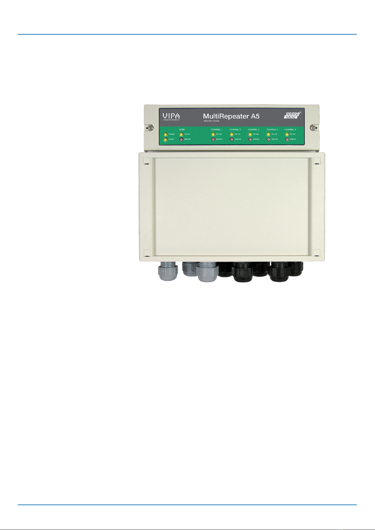
The PROFIBUS MultiRepeater A5 is advanced, flexible and robust network components
for PROFIBUS DP installations, to implement long multi-device spur lines and backbone
structures with star/tree segments.
nPROFIBUS DP is a high speed communication bus that has to comply with strict rules
concerning spur lines, because of possible reflections that could lead to communica-
tion disturbances. If spur lines or star segments are required, costly investments in
repeaters have to be done.
nA innovative component for such applications is the PROFIBUS MultiRepeater A5.
These are perfect economic solutions to implement reliable spur lines in high speed
DP networks. They have the functionality of 5 galvanic isolated transparent repeaters.
This allows network structures with extended spur lines that individually can handle a
maximum of 31 devices and a length equal to the main bus. The MultiRepeater
refresh a received message on one Channel and transfer it to all the other Channels
(chicken foot topology).
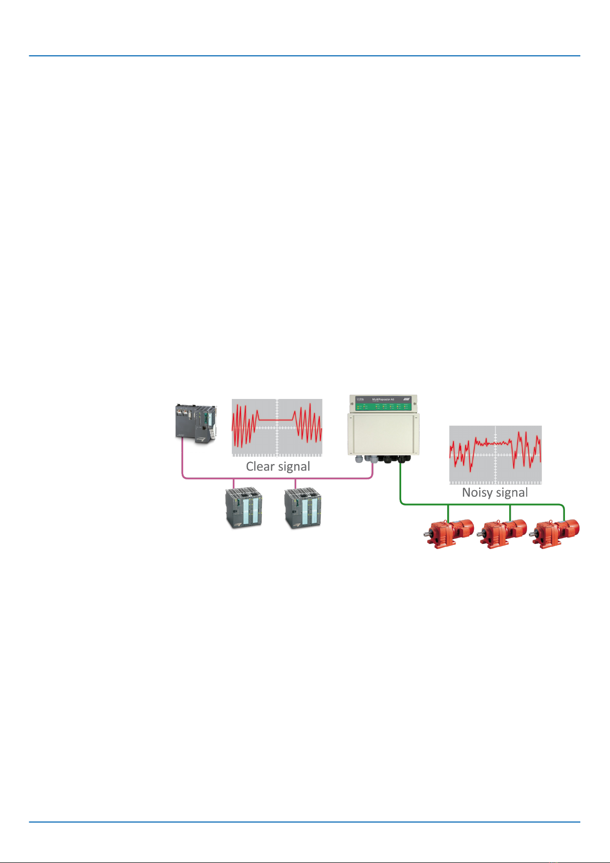
nBecause the PROFIBUS MultiRepeater A5 creates isolated segments, the device can
now be removed and added during operation. Also electrical bus problems and EMC
disturbances in a spur do not spread to the other segments. The intelligent logic and
isolation circuits of the MultiRepeaters do not change the bit width. This means the
MultiRepeaters do not have limitations in serial placement. The logic also detects the
transmission speed automatically.
nTo assist the installation work, termination is integrated and can be switched on/off.
The grounding concept is also selectable: direct or capacitive grounding. The Multi-
Repeaters are powered by a 10 to 32 DC Voltage (110/230V AC versions are also
available). For troubleshooting, maintenance and commissioning the MultiRepeaters
are equipped with a display on the outside, which indicate the status of each Channel
(Data and Error).
VIPA Networking Solutions Product Description
General
HB153 | PBR | 920-1CA50 | en | 19-09 7
2.2 Product features
n5 Galvanic isolated channels (repeater segments)
nTransparent for all PROFIBUS DP protocols
nDP-RS485 specifications for each channel
nCable redundancy for channel 1+2
n9.6 Kbps to 12 Mbps
n31 devices per channel
n1200 m spur line length (depends on transmission speed)
nNo limit in serial placement or cascading of MultiRepeaters
nNo address required
nIntegrated termination facilities (switches)
nConfigurable grounding system (direct or capacitive)
nIP 65 classification
Long spur lines to instruments and the possibility to remove/insert them during operation.
Short circuit protection on each spur line is automatically provided.
VIPA Networking Solutions
Product Description
Product features
HB153 | PBR | 920-1CA50 | en | 19-09 8
2.3 Application areas
nDynamic spur lines to actuators, flow meters and pH analyzers
nRemovable drives and motors
nPull/Plug motor control centres (drawers)
nRoof mounted devices in tank farms
nDirty and humid environments
nBarrier for non-galvanic isolated equipment
nLarge star/tree structured networks
nOutdoor applications with device and cable stress
2.4 Additional Benefits
nHot slave insertion and removal during operation
nShort circuit protection on each Channel
nCompact and robust construction
nStatus and error display (per Channel)
nSuitable for all DP cables
nConveniently arranged networks
nEasy extendable installations
nOn-board DB9 female connector on each channel for maintenance activities
nCost Savings
Because of the isolation and intelligence the PROFIBUS-Multi-Repeater provides, it can
be used as a barrier for electrically sensitive segments. This keeps the backbone and
other Channels clean.
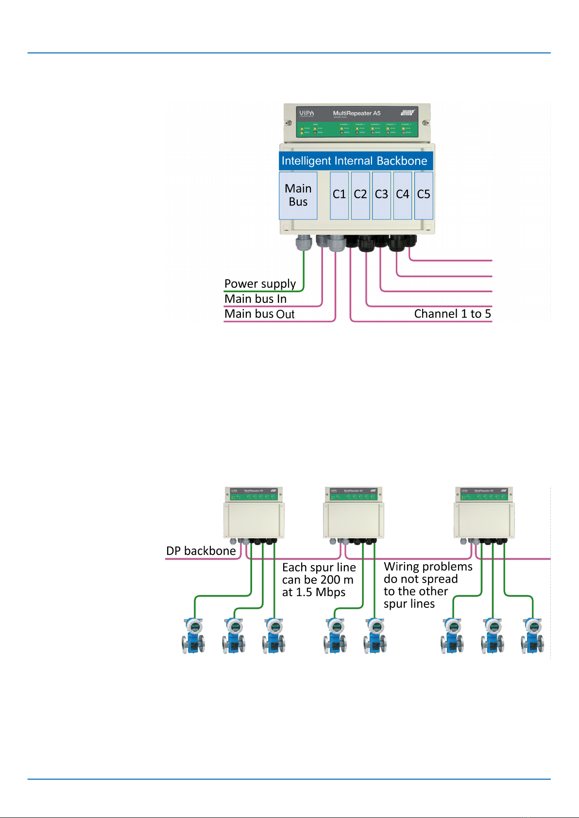
2.5 Channel Structure
Each channel is electrically isolated and internally connected to the transparent intelligent
backbone. The termination is switchable and powered by the MultiRepeater. The
shielding of the PROFIBUS cable can be directly grounded or indirectly grounded.
VIPA Networking Solutions Product Description
Channel Structure
HB153 | PBR | 920-1CA50 | en | 19-09 9
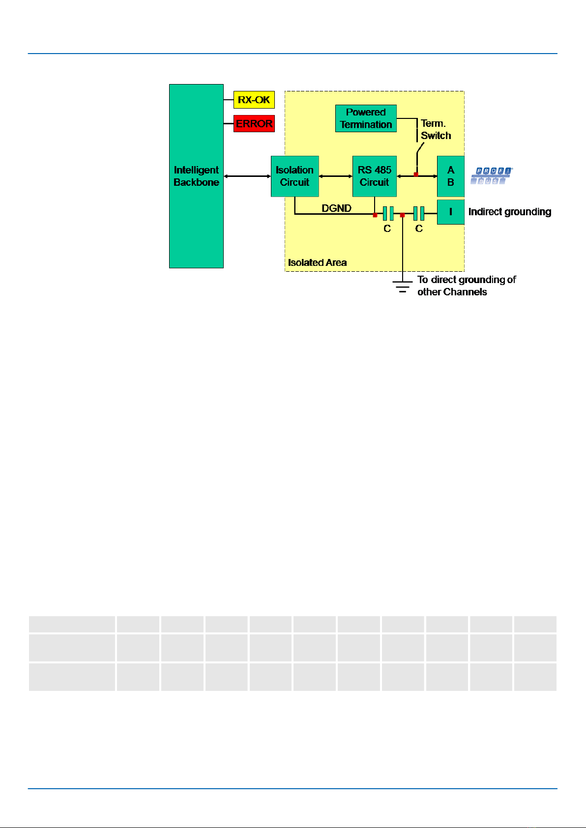
2.6 Grounding System
The PROFIBUS MultiRepeater can be grounded by 3 methods:
nDirect grounding on the Ground Rail
nIndirect grounding (through a capacitor)
nCombination of direct and indirect
The power supply must be grounded directly on the Ground Rail. The shielding of the
PROFIBUS cables can be directly or indirectly grounded. If you do not want to ground all
or some cables to the common ground, i.e. compensating current, the cable shielding
must be connected to pin "I" which stands for Indirect grounding. A capacitor with a par-
allel high value resistor will separate the 2 potentials, ensuring protection of the signal
against non-DC disturbances. If by accident on 1 channel the Direct Grounding is con-
nected with the Indirect Grounding, the connection to the Direct Grounding bypasses the
capacitor in the Indirect Ground connection. The current on the shield will flow to Direct
Ground.
2.7 Cable lengths for PROFIBUS DP
The cables on the channels and the main channel must comply with the PROFIBUS DP
cable specifications for RS485.
Baudrate (kbit/s) 9.6 19.2 45.45 93.75 187.5 500 1500 3000 6000 12000
Segment length
(m)
1200 1200 1200 1200 1000 400 200 100 100 100
Segment length
(feet)
3940 3940 3940 3940 3280 1310 656 328 328 328
VIPA Networking Solutions
Product Description
Cable lengths for PROFIBUS DP
HB153 | PBR | 920-1CA50 | en | 19-09 10
This manual suits for next models
2
Table of contents


