
YASKAWA TP 307-SM User manual

TP-smart | H71-71A41-0 | Manual
HB160 | TP-smart | H71-71A41-0 | en | 20-20
VIPA HMI
smartPanel - TP307-SM

H71-71A41-0_000_TP307-SM,3,EN - © 2020
YASKAWA Europe GmbH
Ohmstraße 4
91074 Herzogenaurach
Tel.: +49 9132 744 0
Fax: +49 9132 744 186
Email: [email protected]
Internet: www.yaskawa.eu.com

Table of contents
1 General.................................................................................................................... 4
1.1 Copyright © YASKAWA Europe GmbH............................................................ 4
1.2 About this manual............................................................................................. 5
1.3 Safety information............................................................................................. 6
2 Hardware description............................................................................................. 7
2.1 Safety information for users.............................................................................. 7
2.2 Properties......................................................................................................... 8
2.3 Structure........................................................................................................... 9
2.3.1 Overview........................................................................................................ 9
2.3.2 Interfaces..................................................................................................... 10
2.3.3 Memory management.................................................................................. 11
2.4 Dimensions..................................................................................................... 12
2.5 General data................................................................................................... 13
2.6 Technical data................................................................................................. 14
3 Deployment........................................................................................................... 17
3.1 Installation...................................................................................................... 17
3.2 Commissioning............................................................................................... 18
3.2.1 Firmware update.......................................................................................... 19
3.2.2 Startup-Manager.......................................................................................... 21
3.3 Connection to a PLC system.......................................................................... 24
3.4 Operating system Windows Embedded Compact 7....................................... 25
3.4.1 General........................................................................................................ 25
3.4.2 Structure...................................................................................................... 26
3.5 Integrated server............................................................................................ 29
3.5.1 General........................................................................................................ 29
3.5.2 ftp server...................................................................................................... 29
3.5.3 Telnet server................................................................................................ 30
3.5.4 VNC server.................................................................................................. 32
3.5.5 Web server.................................................................................................. 33
3.6 Access to the network resources.................................................................... 34
4 Installation Guidelines......................................................................................... 36
4.1 Basic rules for the EMC-equitable assembly of installations.......................... 36
4.2 EMC-equitable assembly................................................................................ 39
4.3 EMC-equitable cabling................................................................................... 40
4.4 Special precautions providing high noise immunity........................................ 43
4.5 Checklist for the EMC-compliant installation of controllers............................. 44
Appendix............................................................................................................... 45
A History of changes............................................................................................ 47
VIPA HMI Table of contents
HB160 | TP-smart | H71-71A41-0 | en | 20-20 3

1 General
1.1 Copyright © YASKAWA Europe GmbH
This document contains proprietary information of YASKAWA and is not to be disclosed
or used except in accordance with applicable agreements.
This material is protected by copyright laws. It may not be reproduced, distributed, or
altered in any fashion by any entity (either internal or external to YASKAWA) except in
accordance with applicable agreements, contracts or licensing, without the express
written consent of YASKAWA and the business management owner of the material.
For permission to reproduce or distribute, please contact: YASKAWA Europe GmbH,
European Headquarters, Hauptstraße 185, 65760 Eschborn, Germany
Tel.: +49 6196 569 300
Fax.: +49 6196 569 398
Email: [email protected]
Internet: www.yaskawa.eu.com
Every effort has been made to ensure that the information contained in
this document was complete and accurate at the time of publishing. Nev-
ertheless, the authors retain the right to modify the information.
This customer document describes all the hardware units and functions
known at the present time. Descriptions may be included for units which
are not present at the customer site. The exact scope of delivery is
described in the respective purchase contract.
Hereby, YASKAWA Europe GmbH declares that the products and systems are in compli-
ance with the essential requirements and other relevant provisions. Conformity is indi-
cated by the CE marking affixed to the product.
For more information regarding CE marking and Declaration of Conformity (DoC), please
contact your local representative of YASKAWA Europe GmbH.
VIPA, SLIO, System 100V, System 200V, System 300V, System 300S, System 400V,
System 500S and Commander Compact are registered trademarks of YASKAWA Europe
GmbH.
SPEED7 is a registered trademark of YASKAWA Europe GmbH.
SIMATIC, STEP, SINEC, TIA Portal, S7-300, S7-400 and S7-1500 are registered trade-
marks of Siemens AG.
Microsoft and Windows are registered trademarks of Microsoft Inc., USA.
Portable Document Format (PDF) and Postscript are registered trademarks of Adobe
Systems, Inc.
All other trademarks, logos and service or product marks specified herein are owned by
their respective companies.
All Rights Reserved
EC conformity declaration
Conformity Information
Trademarks
VIPA HMI
General
Copyright © YASKAWA Europe GmbH
HB160 | TP-smart | H71-71A41-0 | en | 20-20 4

Contact your local representative of YASKAWA Europe GmbH if you have errors or ques-
tions regarding the content of this document. If such a location is not available, you can
reach YASKAWA Europe GmbH via the following contact:
YASKAWA Europe GmbH, Ohmstraße 4, 91074 Herzogenaurach, Germany
Fax: +49 9132 744 29 1204
Email: [email protected]
Contact your local representative of YASKAWA Europe GmbH if you encounter problems
or have questions regarding the product. If such a location is not available, you can reach
the YASKAWA customer service via the following contact:
YASKAWA Europe GmbH,
European Headquarters, Hauptstraße 185, 65760 Eschborn, Germany
Tel.: +49 6196 569 500 (hotline)
Email: [email protected]
1.2 About this manual
This manual describes the VIPA smartPanel H71-71A410-0. It contains a description of
the structure, project engineering and deployment.
Product Order number as of state:
HW FW OS
TP 307-SM H71-71A410-0 01 V1.0.2 WindowsÒ Embedded Compact 7
The manual is targeted at users who have a background in automation technology.
The manual consists of chapters. Every chapter provides a self-contained description of a
specific topic.
The following guides are available in the manual:
nAn overall table of contents at the beginning of the manual
nReferences with page numbers
The manual is available in:
nprinted form, on paper
nin electronic form as PDF-file (Adobe Acrobat Reader)
Important passages in the text are highlighted by following icons and headings:
DANGER!
Immediate or likely danger. Personal injury is possible.
Document support
Technical support
Objective and contents
Target audience
Structure of the manual
Guide to the document
Availability
Icons Headings
VIPA HMI General
About this manual
HB160 | TP-smart | H71-71A41-0 | en | 20-20 5

CAUTION!
Damages to property is likely if these warnings are not heeded.
Supplementary information and useful tips.
1.3 Safety information
The system is constructed and produced for:
ncommunication and process control
ngeneral control and automation tasks
nindustrial applications
noperation within the environmental conditions specified in the technical data
ninstallation into a cubicle
DANGER!
This device is not certified for applications in
– in explosive environments (EX-zone)
The manual must be available to all personnel in the
nproject design department
ninstallation department
ncommissioning
noperation
CAUTION!
The following conditions must be met before using or commis-
sioning the components described in this manual:
– Hardware modifications to the process control system should only be
carried out when the system has been disconnected from power!
– Installation and hardware modifications only by properly trained per-
sonnel.
– The national rules and regulations of the respective country must be
satisfied (installation, safety, EMC ...)
National rules and regulations apply to the disposal of the unit!
Applications conforming
with specifications
Documentation
Disposal
VIPA HMI
General
Safety information
HB160 | TP-smart | H71-71A41-0 | en | 20-20 6

2 Hardware description
2.1 Safety information for users
VIPA-modules make use of highly integrated components in MOS-Technology. These
components are extremely sensitive to over-voltages that can occur during electrostatic
discharges. The following symbol is attached to modules that can be destroyed by elec-
trostatic discharges.
The Symbol is located on the module, the module rack or on packing material and it indi-
cates the presence of electrostatic sensitive equipment. It is possible that electrostatic
sensitive equipment is destroyed by energies and voltages that are far less than the
human threshold of perception. These voltages can occur where persons do not dis-
charge themselves before handling electrostatic sensitive modules and they can damage
components thereby, causing the module to become inoperable or unusable. Modules
that have been damaged by electrostatic discharges can fail after a temperature change,
mechanical shock or changes in the electrical load. Only the consequent implementation
of protection devices and meticulous attention to the applicable rules and regulations for
handling the respective equipment can prevent failures of electrostatic sensitive modules.
Modules must be shipped in the original packing material.
When you are conducting measurements on electrostatic sensitive modules you should
take the following precautions:
nFloating instruments must be discharged before use.
nInstruments must be grounded.
Modifying electrostatic sensitive modules you should only use soldering irons with
grounded tips.
CAUTION!
Personnel and instruments should be grounded when working on electro-
static sensitive modules.
Handling of electrostatic
sensitive modules
Shipping of modules
Measurements and altera-
tions on electrostatic sen-
sitive modules
VIPA HMI Hardware description
Safety information for users
HB160 | TP-smart | H71-71A41-0 | en | 20-20 7
2.2 Properties
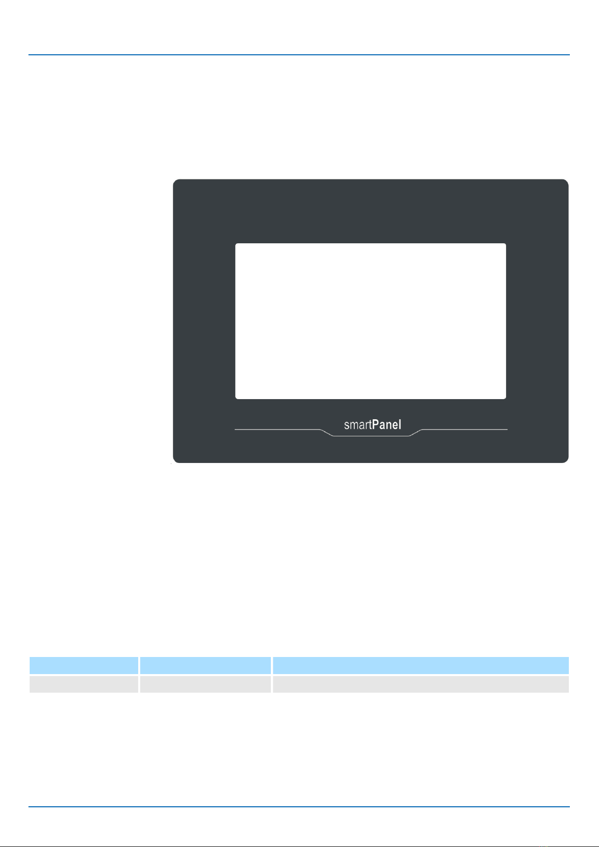
The VIPA smartPanel allows you to visualize and alter operating states and recent
process values of a connected PLC. The smartPanel is a compact and modular
embedded PC based on WindowsÒ EC 7. Besides the extensive WindowsÒ CE functions
the smartPanel offers varied communication possibilities. Here the smartPanel can simply
be configured, controlled and remoted. By including a selectable HMI/SCADA runtime the
smartPanel is particularly suitable for monitoring and controlling of process cycles.
nWindowsÒ Embedded Compact 7
nMovicon 11 CE Standard (4096 I/O Bytes)
nProcessor ARM Cortex A8 1GHz
nFlash memory 4GB, RAM 512MB DDR
nRS232/RS422/RS485, USB-A and Ethernet interface
nRobust plastic case
nDisplay resolution 480 x 800 / 800 x 480, 64K colors
nClock back up (Goldcap)
nResistive analog touch screen
nEasy mounting via mounting clips
nProtection class IP66, Type 2 and 4X (Front) / IP20 (Back)
Order data
Type Order number Description
TP 307-SM H71-71A410-0 7'' TFT color, RS232/RS422/RS485, USB-A, Ethernet RJ45
General
VIPA HMI
Hardware description
Properties
HB160 | TP-smart | H71-71A41-0 | en | 20-20 8

2.3 Structure
2.3.1 Overview
1 Interfaces
2 Display with touch sensitive area (Touch-Screen)
1 USB-A interface USB 2.0
2 RJ45 jack for Ethernet communication LAN
3 RS232/RS422/RS485 interface COM
4 Slot for DC 24V voltage supply
Front view
Bottom view
VIPA HMI Hardware description
Structure > Overview
HB160 | TP-smart | H71-71A41-0 | en | 20-20 9

2.3.2 Interfaces
Using the "Host"-USB-A interface USB mouse, keyboard, stick or USB hard discs can be
connected.
The RJ45 jack provides the interface to the twisted pair cable, required for Ethernet. The
Ethernet interface has got two LEDs for status display.
LEDs
green yellow
Description
on off no link
blinks on 100Mbit/s link
blinks off 10Mbit/s link
9 pin SubD plug
nInterface is compatible to the COM interface of a PC
nLogical signals as voltage levels
nPoint-to-point links with serial full-duplex transfer in two-wire technology up to 15m
distance
nData transfer rate up to 115.2kbit/s
"Host"-USB-A
Ethernet connection
RS232 interface
VIPA HMI
Hardware description
Structure > Interfaces
HB160 | TP-smart | H71-71A41-0 | en | 20-20 10
This manual suits for next models
3
Table of contents
Popular Industrial PC manuals by other brands






Dell
Dell Embedded Box PC 5000 Installation and operation manual

IBASE Technology
IBASE Technology ASB200-918 Series user manual

Lenovo
Lenovo ThinkCentre M90q Hardware Maintenance Manual

IXXAT
IXXAT Econ 100 Hardware manual

Kontron
Kontron KBox A-151-TGL user guide

AXIOMTEK
AXIOMTEK ICO500-518 Series user manual