Yamaha A-S201 User manual

P.O.Box 1, Hamamatsu, Japan
101294
SERVICE MANUAL
INTEGRATED AMPLIFIER
'13.12
A-S201
Copyright (c) Yamaha Corporation All rights reserved.
This manual is copyrighted by Yamaha and may not be copied or
redistributed either in print or electronically without permission.
IMPORTANT NOTICE
This manual has been provided for the use of authorized Yamaha Retailers and their service personnel.
It has been assumed that basic service procedures inherent to the industry, and more specifically Yamaha Products, are already known
and understood by the users, and have therefore not been restated.
WARNING: Failure to follow appropriate service and safety procedures when servicing this product may result in personal injury,
destruction of expensive components, and failure of the product to perform as specified. For these reasons, we advise
all Yamaha product owners that any service required should be performed by an authorized Yamaha Retailer or the
appointed service representative.
IMPORTANT: The presentation or sale of this manual to any individual or firm does not constitute authorization, certification or
recognition of any applicable technical capabilities, or establish a principle-agent relationship of any form.
The data provided is believed to be accurate and applicable to the unit(s) indicated on the cover. The research, engineering, and service
departments of Yamaha are continually striving to improve Yamaha products. Modifications are, therefore, inevitable and specifications
are subject to change without notice or obligation to retrofit. Should any discrepancy appear to exist, please contact the distributor's
Service Division.
WARNING: Static discharges can destroy expensive components. Discharge any static electricity your body may have
accumulated by grounding yourself to the ground buss in the unit (heavy gauge black wires connect to this buss).
IMPORTANT: Turn the unit OFF during disassembly and part replacement. Recheck all work before you apply power to the unit.
■CONTENTS
TO SERVICE PERSONNEL ............................................ 2
FRONT PANEL ...............................................................3
REAR PANELS ...........................................................3–5
REMOTE CONTROL PANEL ..........................................6
SPECIFICATIONS .......................................................6–7
INTERNAL VIEW ............................................................8
SERVICE PRECAUTIONS ..............................................8
DISASSEMBLY PROCEDURES ............................... 9–11
UPDATING FIRMWARE .......................................... 12–17
SELF-DIAGNOSTIC FUNCTION ............................ 18–27
DISPLAY DATA .............................................................28
IC DATA ...................................................................29–31
BLOCK DIAGRAM ........................................................32
WIRING DIAGRAM ....................................................... 33
PRINTED CIRCUIT BOARDS .................................34–39
PIN CONNECTION DIAGRAMS ...................................40
SCHEMATIC DIAGRAM ................................................41
REPLACEMENT PARTS LIST ................................43–49
REMOTE CONTROL .....................................................50
ADVANCED SETUP ......................................................51
A-S201

This product contains chemicals known to the State of California to cause cancer, or birth defects or other reproductive
harm.
DO NOT PLACE SOLDER, ELECTRICAL/ELECTRONIC OR PLASTIC COMPONENTS IN YOUR MOUTH FOR ANY REASON
WHATSOEVER!
Avoid prolonged, unprotected contact between solder and your skin! When soldering, do not inhale solder fumes or
expose eyes to solder/flux vapor!
If you come in contact with solder or components located inside the enclosure of this product, wash your hands before
handling food.
1. Critical Components Information
Components having special characteristics are marked ⚠and
must be replaced with parts having specifications equal to those
originally installed.
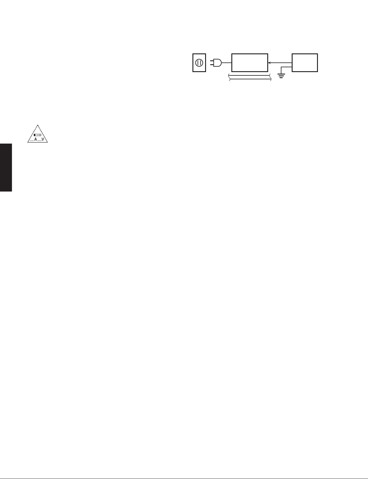
2. Leakage Current Measurement (For 120V Models Only)
When service has been completed, it is imperative to verify
that all exposed conductive surfaces are properly insulated
from supply circuits.
• Meter impedance should be equivalent to 1500 ohms shunted
by 0.15 μF.
■TO SERVICE PERSONNEL
• Leakage current must not exceed 0.5mA.
• Be sure to test for leakage with the AC plug in both polarities.
WARNING: CHEMICAL CONTENT NOTICE!
All of the P.C.B.s installed in this unit and solder joints are soldered using the lead free solder.
Among some types of lead free solder currently available, it is recommended to use one of the following types for the
repair work.
• Sn + Ag + Cu (tin + silver + copper)
• Sn + Cu (tin + copper)
• Sn + Zn + Bi (tin + zinc + bismuth)
Caution:
As the melting point temperature of the lead free solder is about 30°C to 40°C (50°F to 70°F) higher than that of the lead
solder, be sure to use a soldering iron suitable to each solder.
About lead free solder
WALL
OUTLET EQUIPMENT
UNDER TEST
AC LEAKAGE
TESTER OR
EQUIVALENT
INSULATING
TABLE
For U model
“CAUTION”
“F1: FOR CONTINUED PROTECTION AGAINST RISK OF FIRE, REPLACE ONLY WITH SAME TYPE 8A, 125V
FUSE.”
For C model
CAUTION
F1: REPLACE WITH SAME TYPE 8A, 125V FUSE.
ATTENTION
F1: UTILISER UN FUSIBLE DE RECHANGE DE MÉME TYPE DE 8A, 125V.
2
A-S201
A-S201

■FRONT PANEL
T model
R model
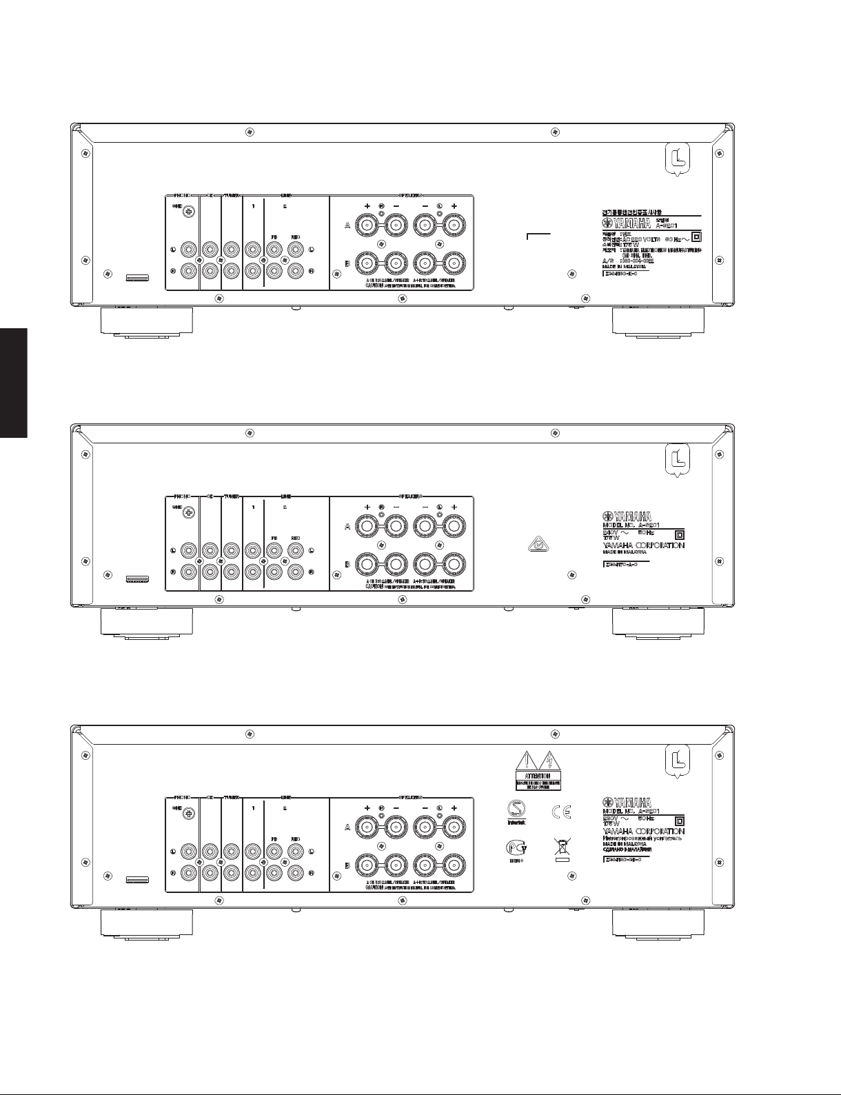
■REAR PANELS
3
A-S201
A-S201

B, G models
K model
A model
4
A-S201
A-S201

L model
5
A-S201
A-S201

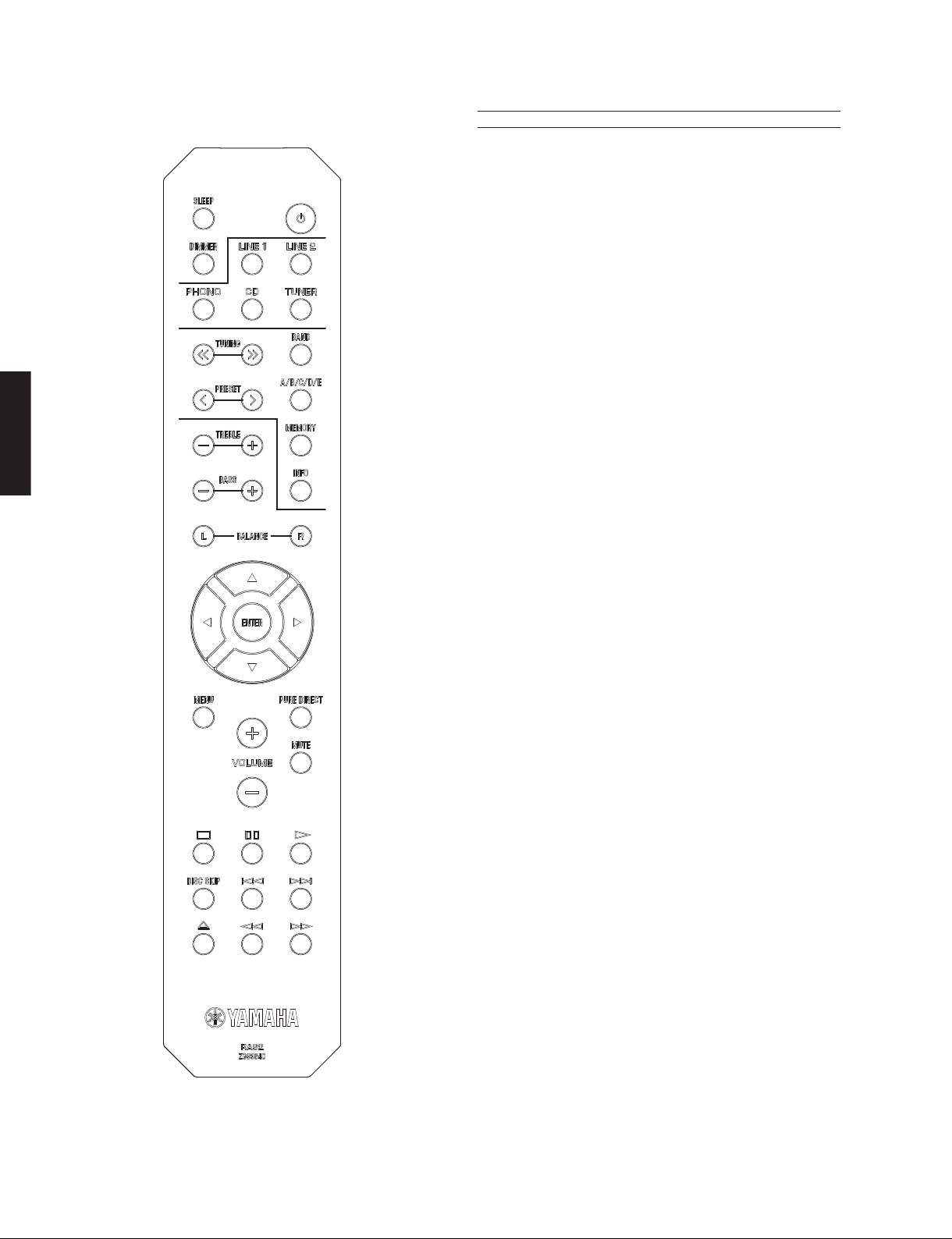
■REMOTE CONTROL PANEL
RAS2 ■Audio Section
Minimum RMS Output Power (Power Amp. Section)
(40 Hz to 20 kHz, 0.2 % THD, 8 ohms / L/R drive)
R, K, A, B, G models .................................................100 W + 100 W
T, L models ...................................................................85 W + 85 W
Dynamic Power Per Channel (IHF) [R, K, A, B, G models]
8 / 6 / 4 / 2 ohms .......................................... 125 / 150 / 165 / 180 W
Maximum Power Per Channel (1 kHz, 0.7 % THD, 4 ohms)
[B, G models]
................................................................................................ 115 W
Maximum Effective Output Power (JEITA)
(1 kHz, 10 % THD, 8 ohms) [R, T, L models]
R model .................................................................................. 140 W
T, L models ............................................................................. 125 W
Input Sensitivity/Input Impedance (1 kHz, 100 W/8 ohms)
PHONO (MM) .................................................. 10.0 mV / 47 k-ohms
CD etc. .............................................................. 500 mV / 47 k-ohms
Output Level/Output Impedance
REC OUT ......................................................... 500 mV / 2.2 k-ohms
Headphone Jack Rated Output/Output Impedance
(1 kHz, 500 mV, 8 ohms load / CD etc. input)
........................................................................... 470 mV / 470 ohms
Frequency Response (CD etc.)
20 Hz to 20 kHz ................................................................ 0 ±0.5 dB
10 Hz to 100 kHz .............................................................. 0 ±3.0 dB
RIAA Equalization Deviation
PHONO (MM) ...................................................................... ±0.5 dB
Total Harmonic Distortion (20 Hz to 20 kHz)
PHONO (MM) to REC OUT (2 V) ..............................0.025 % or less
CD etc. to SP OUT (50 W/8 ohms) ...............................0.2 % or less
Signal to Noise Ratio (IHF-A Network)
PHONO (MM)
Input shorted 10 mV ............................................... 75 dB or more
CD etc. (PURE DIRECT on)
Input shorted 500 mV ........................................... 100 dB or more
Residual Noise (IHF-A Network)
................................................................................................. 70 μV
Tone Control Characteristics
Bass
Boost/Cut (50 Hz) ............................................................... ±10 dB
Turnover frequency .............................................................170 Hz
Treble
Boost/Cut (20 kHz) ............................................................. ±10 dB
Turnover frequency ............................................................ 3.0 kHz
■SPECIFICATIONS
6
A-S201
A-S201

Unit: mm (inch)
■General
Power Supply
R model .......................................AC 110–120/220–240 V, 50/60 Hz
T model ................................................................... AC 220 V, 50 Hz
K model .................................................................. AC 220 V, 60 Hz
A model .................................................................. AC 240 V, 50 Hz
B, G models ............................................................ AC 230 V, 50 Hz
L model ...................................................... AC 220–240 V, 50/60 Hz
Power Consumption
R, K, A, B, G models ............................................................... 175 W
T, L models ............................................................................. 140 W
Standby Power Consumption [T, K, A, B, G, L models]
......................................................................................0.5 W or less
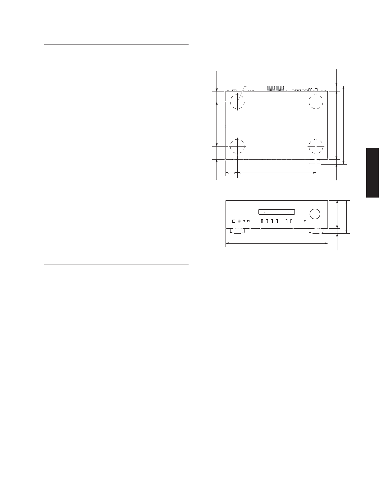
Dimensions (W x H x D)
............................... 435 x 141 x 333 mm (17-1/8" x 5-1/2" x 13-1/8")
Weight
................................................................................ 6.7 kg (14.8 lbs.)
Finish
R, T, K, A, B, G, L models ............................................... Black color
R, T, K, A, B, G, L models ................................................Silver color
Accessories
Remote control ..............................................................................x 1
Battery (LR6, AA, UM-3) ...............................................................x 2
*Specifications are subject to change without notice.
R.....................General model
T..................... Chinese model
K ......................Korean model
A .................Australian model
B.......................British model
G..................European model
L..................Singapore model
•DIMENSIONS
Front view
21
(7/8")
435 (17-1/8")
141 (5-1/2")
120 (4-3/4")
Top view
20.5
(3/4")
22.5
(7/8")
333 (13-1/8")
290 (11-3/8")
55
(2-1/8")
45
(1-3/4")
190 (7-1/2")
ø 60
335 (13-1/4")50
(2")
7
A-S201
A-S201

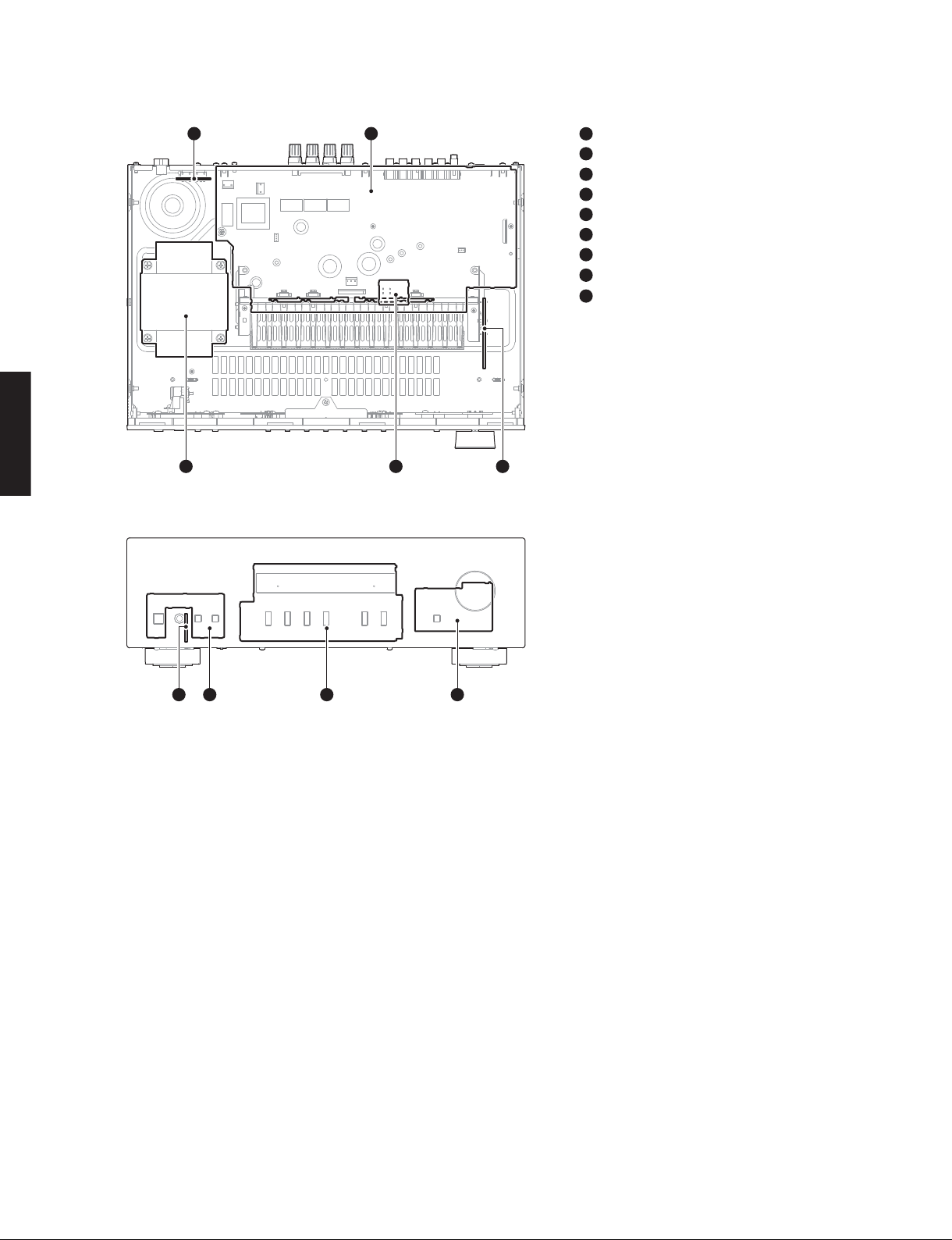
■INTERNAL VIEW
■SERVICE PRECAUTIONS
Safety measures
• Some internal parts in this product contain high voltages and are dangerous.
Be sure to take safety measures during servicing, such as wearing insulating gloves.
• Note that the capacitors indicated below are dangerous even after the power is turned off because an electric charge
remains and a high voltage continues to exist there.
Before starting any repair work, connect a discharging resistor (5 k-ohms/10 W) to the terminals of each capacitor
indicated below to discharge electricity.
The time required for discharging is about 30 seconds per each.
C140, C143, C149 and C150 on MAIN (1) P.C.B.
For details, refer to “PRINTED CIRCUIT BOARDS”.
MAIN (5) P.C.B. (R model)
MAIN (1) P.C.B.
MAIN (8) P.C.B.
MAIN (7) P.C.B.
POWER TRANSFORMER
MAIN (6) P.C.B.
MAIN (3) P.C.B.
MAIN (2) P.C.B.
MAIN (4) P.C.B.
Top view
Front view
4
879
53
6
1
2
3
4
5
6
7
8
9
21
8
A-S201
A-S201

(Remove parts in the order as numbered.)
Disconnect the power cable from the AC outlet.
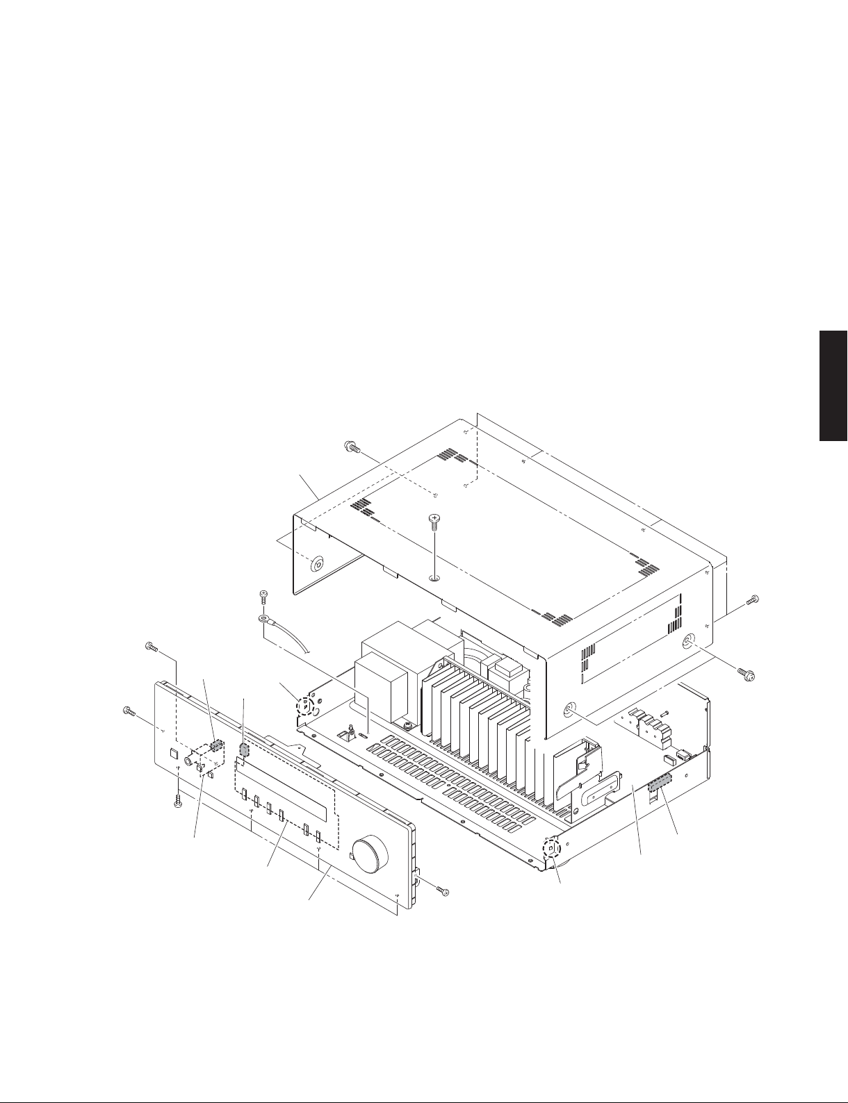
1. Removal of Top Cover
a. Remove screw (①), 4 screws (②) and 6 screws (③). (Fig. 1)
b. Remove the top cover. (Fig. 1)
2. Removal of Front Panel Unit
a. Remove screw (④) and 6 screws (⑤). (Fig. 1)
b. Remove screw (⑥) and then remove W501. (Fig. 1)
c. Remove CB102, CB204 and CB502. (Fig. 1)
d. Release 2 hooks and then remove the front panel unit. (Fig. 1)
Fig. 1
■DISASSEMBLY PROCEDURES
Front panel unit
Top cover
CB102
CB502
CB204
MAIN (2) P.C.B. MAIN (1) P.C.B.
MAIN (6) P.C.B.
Hook
Hook
①
④
④
⑤
⑤
②
②
③
⑤
9
A-S201
A-S201

Fig. 3
Fig. 2
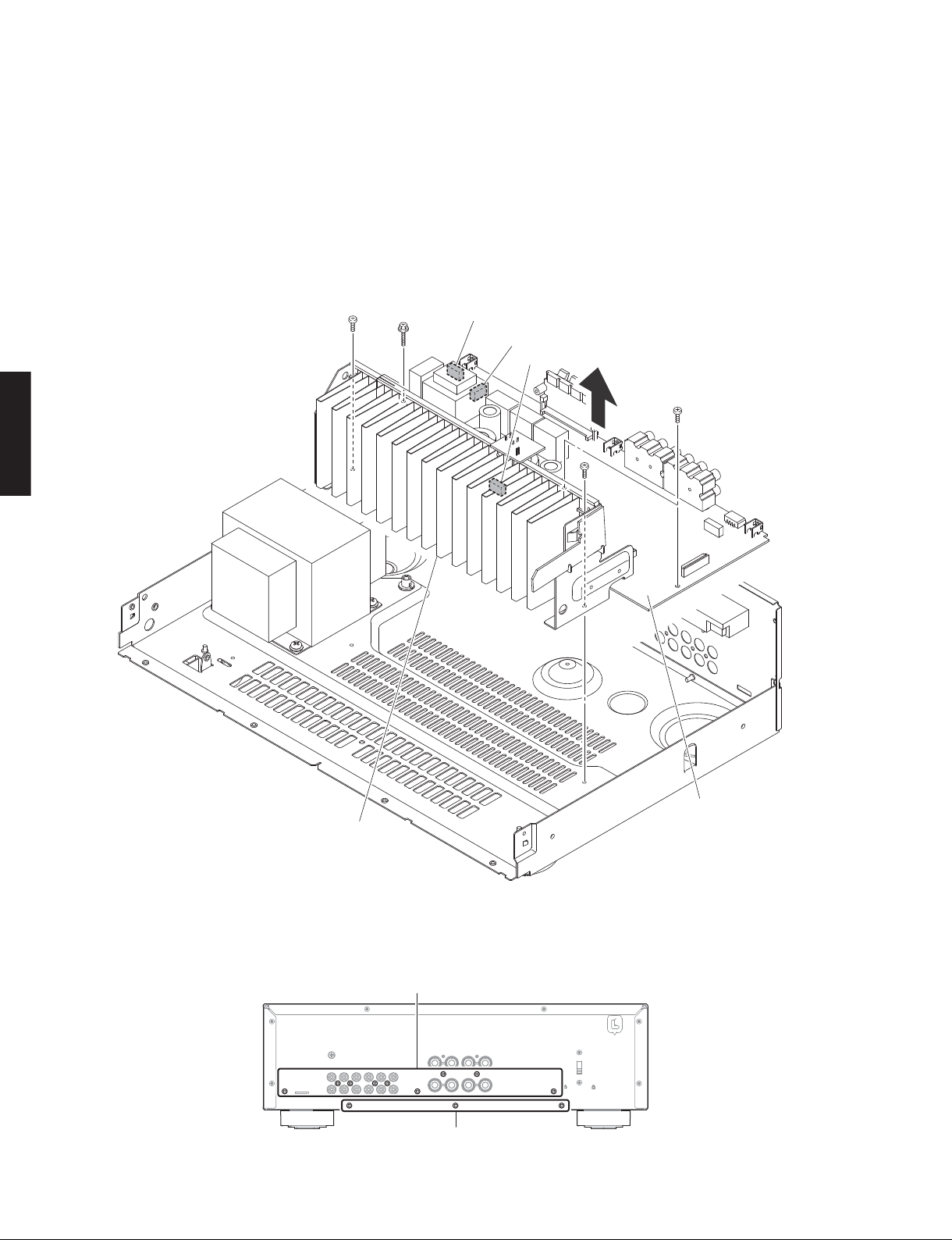
3. Removal of AMP Unit
a. Remove 12 screws (⑦). (Fig. 3)
b. Remove 4 screws (⑧) and screw (⑨). (Fig. 2)
c. Remove CB4, CB7 and CB103. (Fig. 2)
d. Remove the AMP unit. (Fig. 2)
AMP unit
CB4
CB7
CB103
MAIN (1) P.C.B.
⑧
⑧
⑧⑨
Rear view
⑦
⑦
10
A-S201
A-S201
Other manuals for A-S201
2
This manual suits for next models
1
Table of contents
Other Yamaha Amplifier manuals

Yamaha
Yamaha AV-55 User manual

Yamaha
Yamaha HA8 User manual

Yamaha
Yamaha AX-497 User manual

Yamaha
Yamaha RX-V557 User manual

Yamaha
Yamaha DSP-A595a User manual

Yamaha
Yamaha MX-55 User manual

Yamaha
Yamaha A-S701 User manual

Yamaha
Yamaha PD2500 User manual

Yamaha
Yamaha MX-A5200 User manual

Yamaha
Yamaha AX-930 User manual

Yamaha
Yamaha P2160 User manual

Yamaha
Yamaha AX-900 User manual

Yamaha
Yamaha P2700 User manual

Yamaha
Yamaha PC5002M User manual

Yamaha
Yamaha A-1020 User manual

Yamaha
Yamaha XP1000 User manual

Yamaha
Yamaha P2100 User manual

Yamaha
Yamaha P5000S - Amplifier User manual

Yamaha
Yamaha AX-892 User manual

Yamaha
Yamaha A-S700 - Amplifier User manual