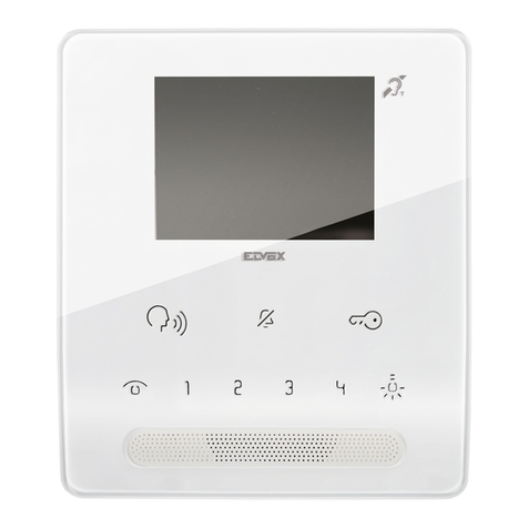
WRT TZS-801ZCD8S7 User manual

Instruction (Version: H2)
Thank you for choosing WRT. Please read this manual before
using. WRT reserves the right to change specifications or designs
described in this manual without notice and obligation.
TZS-801ZCD8S7
A/A,H
Identifier

Content
Content
1.0 Features & Functions
2.0 Equipment Description
3.0 Caution
4.0 Installation
5.0 Operation
6.0 Specification
7.0 Terminal Description
8.0 Trouble Shooting
9.0 Wiring
1
3
2
4
5-28
29
30
31
32

Features & Functions
1
801 intercom systems is composed by building gate station, user door phone, PC and other
equipments, which is based on TCP/IP. The system is with the technology of multichannel, every
channel can work independently.
1. Suit for large community
2. Both mirror and aluminum appearances for select, wall hanging or wall mounted install.
3 . 7.0” LCD Display, monitor the situation of the entrances
4. Remote unlock
5. Can call the Control Center; Control Center can know through the station if there is any
emergence
6. Call the other tenant for intercom
7. Ringtone Download and Silent Mode
8. Function for lift
9. Divert
10. Home furnishings control (only for the Home Extension)
11. Check pictures, SMS ect.
12. Service for the convenience of the customers from the Control Centre is supported
13. Parallel Operation is allowed, at most 4 Indoor Monitors can be work together
14. Remote update

Equipment Description
2
Front View Back View
4
3
5
10
11
8
9
7
15
14
13
12
16
17
6
1
2
1. 2. 3. 4Microphone Indicator LED Build-in Volume Adjustment .Alarm 5.Lift 6.Screen
7.Speaker 8. Network port 9.Pin Socket for Alarm mode 10. Pin Socket for Alarm Detector
11.Socket of Alarm Detector 12. Socket of lift 13. External Socket for the power of emergence and alarm
select 14. Socket for Unit Module(Type:A,H) 15. Connection Socket for audio and data of the Front Door
Station 16. Connection Socket for video of the Front Door Station 17. Connect Socket for output of +180VDC
18. Socket for Fire Detector/PIR+12VDC/0.5A power output
2
1
GND
+18V
V- IN
48 5-B
485-A
AU -OU T
AU-I N
GN D
GND
+12VDC
8 7 6 5 4 3 2 1
8 7 6 5 4 3 2 1
烟感
GND
红外
报警 输入
GN D
报警 输出
18
TZS-801ZCD8S7

1. Do not install the stations in any of the following locations, as it can cause fire, electric shock or unit damage:
·High or extreme cold temperature area, under direct sunlight, near equipment that varies in temperature, in front of
air conditioner, inside a refrigerated area, etc.
·Places subject to moisture or humidity extremes ( bathroom, cellar, greenhouse, etc. )
·Places subject to environmental conditions, such as oil, dust, chemicals, salt, etc.
·Places subject to constant vibration or impact.
·Where noise-generating devices such as TV or radio are close by.
·Places subject to steam or smoke. (Near heating equipment or cooking surfaces)
2. Be sure to cut off the power during installation.
3. Do not attempt to change or alter the equipment. It can cause fire or electric shock.
4. Do not plug or unplug with wet hands. Electric shock could result.
5. Do not use any power source other than specified. Fire or electric shock could result.
6. Make sure wires are connected properly before plugging in power supply.
7. If the system is found of any malfunction, please cut off the power and inspect according to the Trouble Shooting. If it is
unable to find the causes, please contact the sales agent or the manufacturer's after-sales service department. Do not repair
or replace the parts by yourself, otherwise the system might be damaged.
80c m
900
140cm
145cm
130cm
130 cm
Caution
3
Caution

Installation
4
Installation
1. Make a hole in the wall prefer to the dimension of 86.0mm×86.0mm×30.0mm wall box. The bottom of
the hole shall be 145mm above the ground.(This depends on the individual's height). Make a hole in
the wall box and insert the wires into the wall box through the inlet. (Figure 1)
2. Make 4 screw holes according to the positioning card, and then drive the cement plugs into the 4 screw
holes through the inlet. (Figure 2)
3. Use flat tool to open the front decorative cover. (Figure 3)
4. After connecting door phone wires, fix the door station on the wall with 4 screws. (Figure 4)
5 .Fix the cover.
hole
wall
86 box
Figure 1Figure 2
Figure 3 Figure 4
wall
Prize up Prize up
wall
plotting sheet
86 box
154.0
230.0
96.0
53
86.0

5
Operation
Operation
This station is operated by touching the key.It will boot normally after 30 seconds when it is energized.
The Status LED will turn to green when standby. Touch the screen when it is in standby state, and can operate
it again.
There are service, Monitor,Smart home,Call,Message,Home,Settings,Help icons in homepage.Touch can
turn off the screen, it will turn in screen saver or shut down if there is no operating after 3 mins.
Settings
Specification of the door phone must be set after connect well. Press “setting” icon, turn to the interface where
you can set password, room number and so forth.
Password
Touch the icon of “Password”, and input the old password (input the PIN “88888888” for first usage), and press

6
Operation
Operation
“#” key to confirm. If you forget the password, you can restore it to PIN through the Control Center.
Alarm
There are two lines of alarm LEDs show on the up right side of the main interface. The arm is turned off when
it is black; arm zones are not set up when it is green;arm zones are set up when it is yellow;there is a new
alarm when it is red.
8 Alarm Zones in all, Zones 1 to 4 are for fire, gas, FIR and door sensor, 5 to 8 would be set by your own.
You have to set up the arm zones first.
Touch the “Alarm” icon, input the password and press “#” to confirm.
Touch “Alarm Zone” icon, click the zones to arm them and click √ to confirm, click the armed zones again to
disarm them. Click ← to return to previous menu.

Ring
Set ringtones for outwall station,gate station,outdoor station, intercommunication indoor monitors,
alarm,message etc.Click”Ring”
Alarm all: Click “Alarm all” and click √ to confirm.
Disarm all: Click “Disarm all” and click √ to confirm.
Note: Smoke and Gas zones will turn to arming status after setup.
Arm/Disarm: it works only if it is “home” mode. Click the arm zone you need, and press √ , if “toot” sound is
heard, the alarm LED turns to yellow. Click again the armed zone(s) you want to disarm and click √ to
confirm for disarm purpose.
7
Operation
Operation

: Delete all ringtones (except for the default ring and locking ring)
: Delete the selected ringtones (locked ringtones can't be deleted)
/ : Lock/Unlock the selected ringtones.
: Play the selected ringtone.A dialogue box will show after click to remind user whether to set it.
and : Slip up/down to check other ringtones.
Select the call in locations by “ ” or “ ”, and press √ to confirm,press ←to back to previous
menu.
Option Guard center
Ring
8
Operation
Operation
Table of contents
Other WRT Intercom System manuals