Wolf CT15E/S Operating manual
© WOLF APPLIANCE, INC. 2008 ALL RIGHTS RESERVED Job Aid #802986 Revision E - 2008
SIM HIGH
OFF ON
SIM HIGH
OFFON
SIMHIGH
OFFON
OFF ON
SIM HIGH
ZONE2
HIGH
SIM
ZONE2
OFFON
OFF
O
SIM HIGH
OFF ON
SIM HIGH
OFFON
OFF ON
SIM HIGH
ZONE2
OFF ON
SIM HIGH
ZONE 2
OFF
O
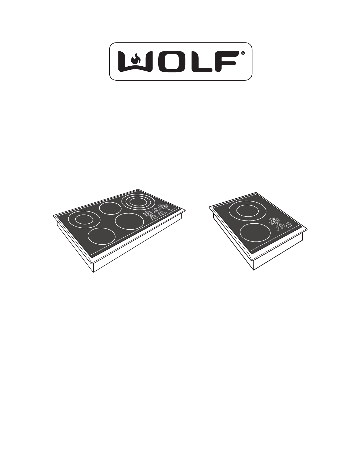
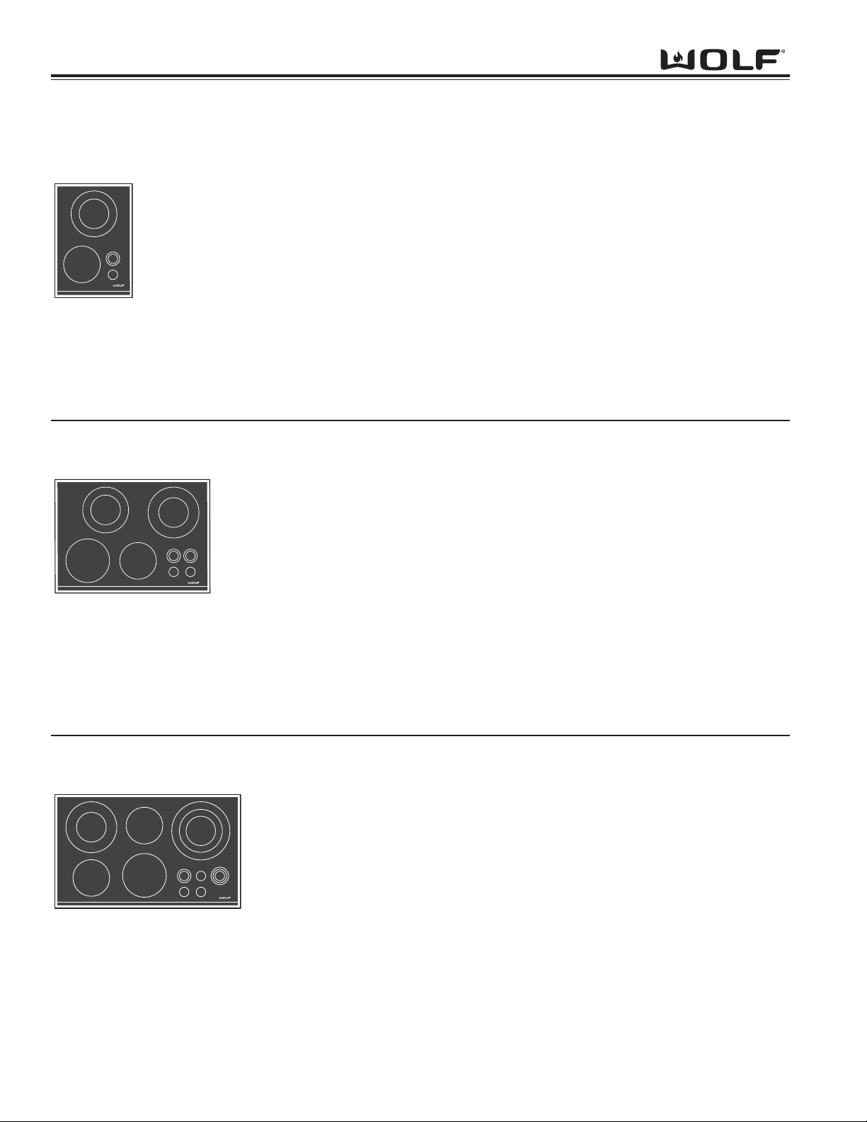
Electric Cooktops
15 Inch
30 Inch
36 Inch
S
I
M
H
I
G
H
O
FF
O
N
O
FF
O
N
S
I
M
H
I
G
H
Z
O
N
E
2
O
FF
O
Technical Service Manual
(Including Parts and Exploded Views)


General Information
EElleeccttrriiccCCooookkttooppss
1-1
SECTION 1
GENERAL INFORMATION
General Information EElleeccttrriiccCCooookkttooppss
1-2
INTRODUCTION
This Wolf Electric Cooktop Technical Service Manual, Part #802986, has been compiled to provide the most recent
technical service information about the Wolf Gas Cooktops. This information will enable the service technician to
troubleshoot and diagnose malfunctions, perform necessary repairs and return a Wolf Gas Cooktop to proper opera-
tional condition.
The service technician should read the complete instructions contained in this Service/Training Manual before initiat-
ing any repairs on a Wolf Appliance.
* Some information in Section 2, Theory of Operation, has been provided by the American Gas Association
and reprinted with their approval.
IMPORTANT SAFETY INFORMATION
Below are the Product Safety Labels used in this manu-
al. The "Signal Words" used are WARNING and
CAUTION.
Please note that these safety labels are placed in areas
where awareness of personal safety and product safety
should be taken and lists the precautions to be taken
when the signal word is observed.
TECHNICAL ASSISTANCE
If you should have any questions regarding a Wolf
appliance and/or this manual, please contact:
Wolf Appliance, Inc.
ATTN: Service Department
P.O. Box 44988
Madison, WI 53744-4988
Customer Service
Phone #: (800) 332 - 9513
Technical Assistance
Phone #: (800) 919 - 8324
Parts / Warranty Claims
Phone #: (800) 332 - 9513
Customer Service E-Mail Address
Customer Service & Technical Assistance
Facsimile #: (608) 441 - 5887
Parts / Warranty Claims
Facsimile #: (608) 441 - 5886
Office Hours:
7:00 AM to 7:00 PM Central Standard Time
Monday through Friday
This manual is designed to be used by Authorized Service Personnel only. Wolf Appliance, Inc.. assumes
no responsibility for any repairs made to Wolf appliances by anyone other than Authorized Service
Technicians.
INDICATES THAT HAZARDOUS OR UNSAFE PRAC-
TICES COULD RESULT IN SEVERE PERSONAL
INJURY OR DEATH
Indicates that hazardous or unsafe practices could
result in minor personal injury or product and/or
property damage
In addition, please pay attention to the signal word
“NOTE”, which highlights especially important informa-
tion within each section.
The information and images are the copyright property of Wolf Appliance, Inc., an affiliate of Sub-Zero, Inc. Neither
this manual nor any information or images contained herein may be copied or used in whole or in part without the
express written permission of Wolf Appliance, Inc., an affiliate of Sub-Zero, Inc. © Wolf Appliance, Inc. all rights
reserved.

General Information
EElleeccttrriiccCCooookkttooppss
1-3
Section 5 -Troubleshooting Guide (Continued)
Possible Error Codes......................................................... 5-6
Troubleshooting Guide....................................................... 5-7
Troubleshooting Guide Table of Contents...................... 5-7
A.Glass Top Assembly................................................... 5-8
Discoloration........................................................ 5-8
Cracks/Chips......................................................... 5-8
B. LED’s On Keypad DO NOT Illuminate and the
Surface Unit DOES NOT Heat.................................. 5-8
C. LED’s On Keypad DO NOT Illuminate and the
Surface Unit DOES Heat........................................... 5-8
D. LED’s On Keypad DO Illuminate and Surface Unit(s)
DO NOT Heat............................................................. 5-8
E. Surface Units DOES NOT Heat But
Control Display Works................................................ 5-8
F. Hot Surface Indicator Light DOES NOT Light Up...... 5-8
G. Hot Surface Indicator Light Stays On......................... 5-8
H. Cooling Fan DOES NOT Come On............................ 5-9
I. Cooling Fan DOES NOT Shut Off.............................. 5-9
J. Heating Elements DO NOT Heat Properly................. 5-9
K. Heating Elements Cycle Off when set to Full Power. 5-9
L. Some Keypads Respond and Some Keypads
DO NOT Respond...................................................... 5-9
M. Some Display Sections Work and Some
Display Sections DO NOT.......................................... 5-9
N. NO Tone when Pressing Keypads............................. 5-9
O. Error Code 1 Ambient Temperature High................... 5-9
P. Error Code 2 Heatsink Teperature High....................... 5-9
Q. Error Code 3 Ambient and Heatsink
Temperature High....................................................... 5-9
R. Error Code 4 Ambient Thermistor Open.................... 5-9
S. Error Code 5 Heatsink Thermistor Open................... 5-10
T. Error Code 6 Sensor Short......................................... 5-10
U. Error Code 7 Element Supervisor Fail....................... 5-10
V. Error Code 8 Glass-touch Keypad Fail...................... 5-10
W. Error Code 9 Off Key Error........................................ 5-10
Section 6 - Technical Data
Wattage / Ohm Data Chart................................................ 6-2
Power Percentage by Number of LEDs Illuminated......... 6-2
Surface Unit Ring Diameter Chart.................................... 6-2
Section 7 - Wiring Diagrams
15” Electric Cooktop Wiring Diagram................................ 7-2
30” Electric Cooktop Wiring Diagram................................ 7-3
36” Electric Cooktop Wiring Diagram................................ 7-4
Section 8 - Parts Lists and Eploded Views
CT15E Parts Lis................................................................ 8-2
CT15E Exploded View...................................................... 8-3
CT30E Parts List............................................................... 8-4
CT30E Exploded View...................................................... 8-5
CT36E Parts Lis................................................................ 8-6
CT36E Exploded View...................................................... 8-7
CT30EU Parts List............................................................ 8-8
CT30EU Exploded View................................................... 8-9
CT36EU Parts List............................................................ 8-10
CT36EU Exploded View................................................... 8-11
TABLE OF CONTENTS
Page # Page #
Section 1 - General Information
Introduction......................................................................... 1-2
Important Safety Information.............................................. 1-2
Technical Assistance...........................................................1-2
Table of Contents................................................................1-3
Warranty Information.......................................................... 1-4
Serial Tag Location............................................................. 1-4
Model Number Key.. .......................................................... 1-5
Model Configurations.......................................................... 1-6
Model Features................................................................... 1-7
Section 2 - Installation Information
Electrical Requirements...................................................... 2-2
Maximum Connected Load................................................. 2-2
Pre-Installation Specifications........................................... 2-3
Countertop Location........................................................ 2-3
Overhead Cabinet Dimensions....................................... 2-3
Installation of Multiple Units............................................... 2-3
Installation Dimensions....................................................... 2-4
Area Requirements......................................................... 2-4
Installation Procedures....................................................... 2-5
CT30EU Flushmount Installation Dimensions.....................2-6
CT36EU Flushmount Installation Dimensions.....................2-7
Filler Strip Installation Procedure....................................... 2-8
Support Kit for DownDraft Installation Procedure.............. 2-9
Section 3 - Operation Information
Control Operation............................................................... 3-2
Residual Heat Indicators.....................................................3-2
Modes of Operation............................................................ 3-2
Lock Mode....................................................................... 3-2
Idle Mode......................................................................... 3-2
Single Element Operation................................................3-3
Dual Element Operation.................................................. 3-3
Triple Element Operation................................................. 3-3
Universal OFF Key.......................................................... 3-3
Cookware Selection............................................................ 3-4
Section 4 - Component Access and Removal
Warnings and Cautions...................................................... 4-2
Flushmount Installation Removal........................................4-3
Glass Top........................................................................... 4-4
Control Board..................................................................... 4-4
Surface Units...................................................................... 4-4
Inner Burner Box................................................................ 4-4
Power Board ...................................................................... 4-5
Terminal Block.................................................................... 4-5
Transverse Blower.............................................................. 4-5
Section 5 -Troubleshooting Guide
Mode 4 Checking the Ambient Temperature of
Thermistor on Power Board............................................ 5-2
Mode 5 Checking Heat Sink Thermistor
on Power Board ............................................................. 5-3
Mode 6 Checking the Lid Switch on the Cover.............. 5-3
Mode 7 Last Error Code Recorded to Eeprom.............. 5-3
Mode 8-14 Preceding Error Code Recorded to Eeprom..5-3
Mode 15 Checking Software Version........................... 5-3
Interpreting Hex Decimal Code......................................... 5-4
Temperature °C / Hex Decimal Chart............................... 5-5
General Information EElleeccttrriiccCCooookkttooppss
1-4
WARRANTY INFORMATION
This page contains a summary of the 2 & 5 Year
Warranty that is supplied with every Wolf product, fol-
lowed by details and notes about the warranties.
TWO & FIVE YEAR Warranty Summary
• Two year TOTAL PRODUCT warranty, parts and
labor.
• Limited Parts Only Warranty for the 3rd through 5th
year on the following parts only:
Electric Heating Elements
Electronic Control Boards
Warranty Details:
The warranty applies only to products installed for
normal residential use. The warranty applies only to
products installed in the United States or Canada.
Warranty Notes:
• All warranties begin at the time of the units initial
installation.
• All Warranty and Service information collected by
Wolf Appliance, Inc.. is arranged and
stored under the unit serial number and/or the
customer’s name. Please note that Wolf Appliance,
Inc., requests that you have the model
serial number available whenever contacting
the factory or parts distributor.
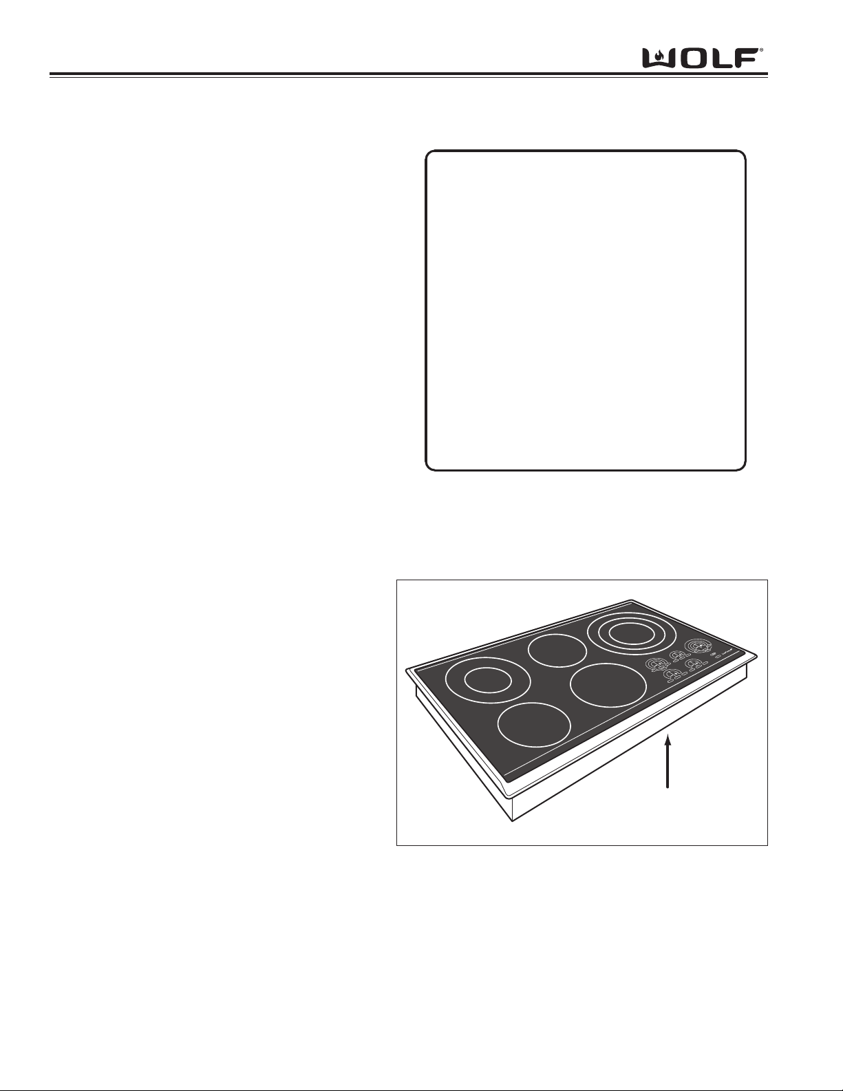
• See Figure 1-1 for serial tag layout.
• See Figure 1-2 for serial tag location.
Wolf Appliance Company, LLC
FITCHBURG, WI
VOLTS : 240/208 KW :
Hz : 60
MODEL# : SERIAL# :
FOR HOUSEHOLD USE ONLY
"Do Not Immerse in Water" "Ne pas plonger dans l'eau"
802926
Figure 1-1 Typical Serial Tag Layout
SIM HIGH
OFFON
SIM HIGH
OFFON
SIM HIGH
OFF ON
OFFON
SIMHIGH
ZONE 2
HIGH
SIM
ZONE2
OFFON
OFF
O
Serial Tag location
Figure 1-2 The serial tag is located on the bottom of the
cooktop.

General Information
EElleeccttrriiccCCooookkttooppss
1-5
MODEL NUMBER KEY
Refer to this key for an example of the model numbers.
Model: CT 36 E / S
Product Type
Size
Fuel
Feature (If Applicable)
Finish
Product Type
CT Cooktop
IM Integrated Gas
Multifunction Cooktop
IG Integrated Grill Cooktop
IS Integrated Steamer Cooktop
IF Integrated Fryer Cooktop
Size
15 15 - inch wide unit
30 30 - inch wide unit
36 36 - inch wide unit
Fuel
EElectric
GNatural Gas
LP Propane Gas (Propane Gas will be indicated by -LP at the end of the model number. Example: CT36G/S-LP)
Finish
SClassic Stainless Steel
PPlatinum Stainless Steel (Not Available for IM, IG, IS and IF)
BCarbon Stainless Steel (Not available for gas models. Not available for IM, IG, IS and IF)
General Information EElleeccttrriiccCCooookkttooppss
1-6
MODEL CONFIGURATIONS
Model Numbers Descriptions
CT30E/S Cooktop 30” Electric Stainless Steel Trim
CT30E/B Cooktop 30” Electric Carbon Stainless Steel Trim
CT30E/P Cooktop 30” Electric Platinum Stainless Steel Trim
CT30E/U Cooktop 30” Electric Unframed
• Four heating elements with six zones
• Two dual elements
2200W outer / 750W inner
1900W outer / 950W
• Two single elements
1500W and 1200W
30” Electric
36” Electric
Model Numbers Descriptions
CT36E/S Cooktop 36” Electric Stainless Steel Trim
CT36E/B Cooktop 36” Electric Carbon Stainless Steel Trim
CT36E/P Cooktop 36” Electric Platinum Stainless Steel Trim
CT36E/P Cooktop 36” Electric Unframed
• Five heating elements with eight zones
• Triple element
2700W outer / 2200W middle / 1050W inner
• Dual elements
2200W outer / 750W inner
• Three single elements
1800W, 1500W & 1200W
Model Numbers Descriptions
CT15E/S Cooktop 15” Electric Stainless Steel Trim
• Two heating elements with three zones
• Dual element
2200W outer / 750W inner
• Single element
1200W
15” Electric

General Information
EElleeccttrriiccCCooookkttooppss
MODEL FEATURES
• Ribbon-type radiant heating elements in various sizes.
• Dual element radiant heater allows for flexible cooking needs.
• Illuminated control lighting.
• Graduated control lighting.
• Lock key and universal off.
• True simmer setting on all elements.
• Melt setting on one element.
• Hot surface indicators on all elements.
• Finishes available include classic, carbon and platinum stainless steel.
• Fast power cycles eliminate long durations of ON/OFF cycles used to control cooking temperature.
• Temperature limiter to ensure that safe operating temperature of glass ceramic is never exceeded.
1-7

Gerneral Information EElleeccttrriiccCCooookkttooppss
1-8
Other manuals for CT15E/S
6
This manual suits for next models
11
Table of contents
Other Wolf Cooktop manuals

Wolf
Wolf CI365T/S User manual

Wolf
Wolf CT15E/S Instructions for use

Wolf
Wolf ci365 User manual

Wolf
Wolf CE304C/B/208 User manual

Wolf
Wolf CG365P/S User manual

Wolf
Wolf Gas cooktop User manual

Wolf
Wolf CI243C/B User manual

Wolf
Wolf CT30IU User manual

Wolf
Wolf ICBMM15T/S User manual

Wolf
Wolf CT15G/S Owner's manual